TM 3-4230-237-10
0002 00
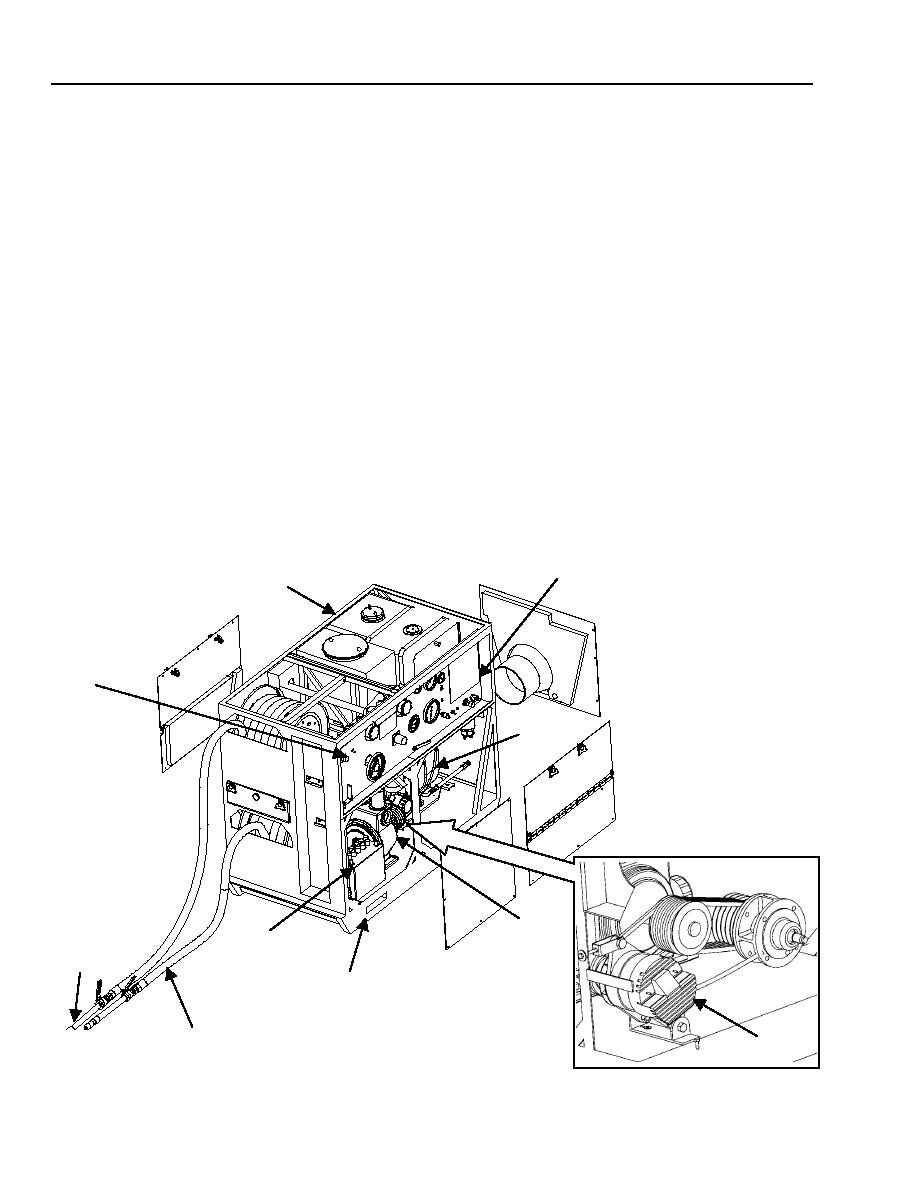
CONTROL PANEL (5). Contains all the gages and valves for operating the engine and for controlling pump delivery.
DIESEL ENGINE (6). The 19 hp engine supplies power through a pulley and four drive belts to drive the pump and through a
pulley and one drive belt to drive the alternator.
FRAME ASSEMBLY (7). A welded steel frame that supports components of the pump unit.
PUMP (8). Pumps fluids from water source to tank unit and then, if needed, to water heater. Also mixes detergent or foam from
the prime detergent tank with water.
24-VOLT BATTERY (9). Provides electrical energy to start the engine.
SKID ASSEMBLY (10). Provides a base for the pump unit assembly, and provides a means to forklift the entire unit.
GUN ASSEMBLIES (11). Consist of either a water, slurry, or foam nozzle on an extension pipe with a ball valve. Controls water
flow.
DISCHARGE HOSES (12). Stored on the two hose reels. The hoses discharge fluid for decontamination, firefighting, or for
showers.
HEATER RECEPTACLE AND SWITCH (13). The water heater's main electrical power cable connects to the socket receptacle
on the pump unit control panel.
ALTERNATOR (14). Supplies power to the water heater through the pump unit control panel. Recharges the 24-volt battery while
the equipment is operating.
5
7
13
6
8
9
11
10
12
14
0002 00-2

