TM 3-4230-237-10
0002 00
Water Heater
3
1
2
2
10
4
5
2
9
2
7
8
6
11
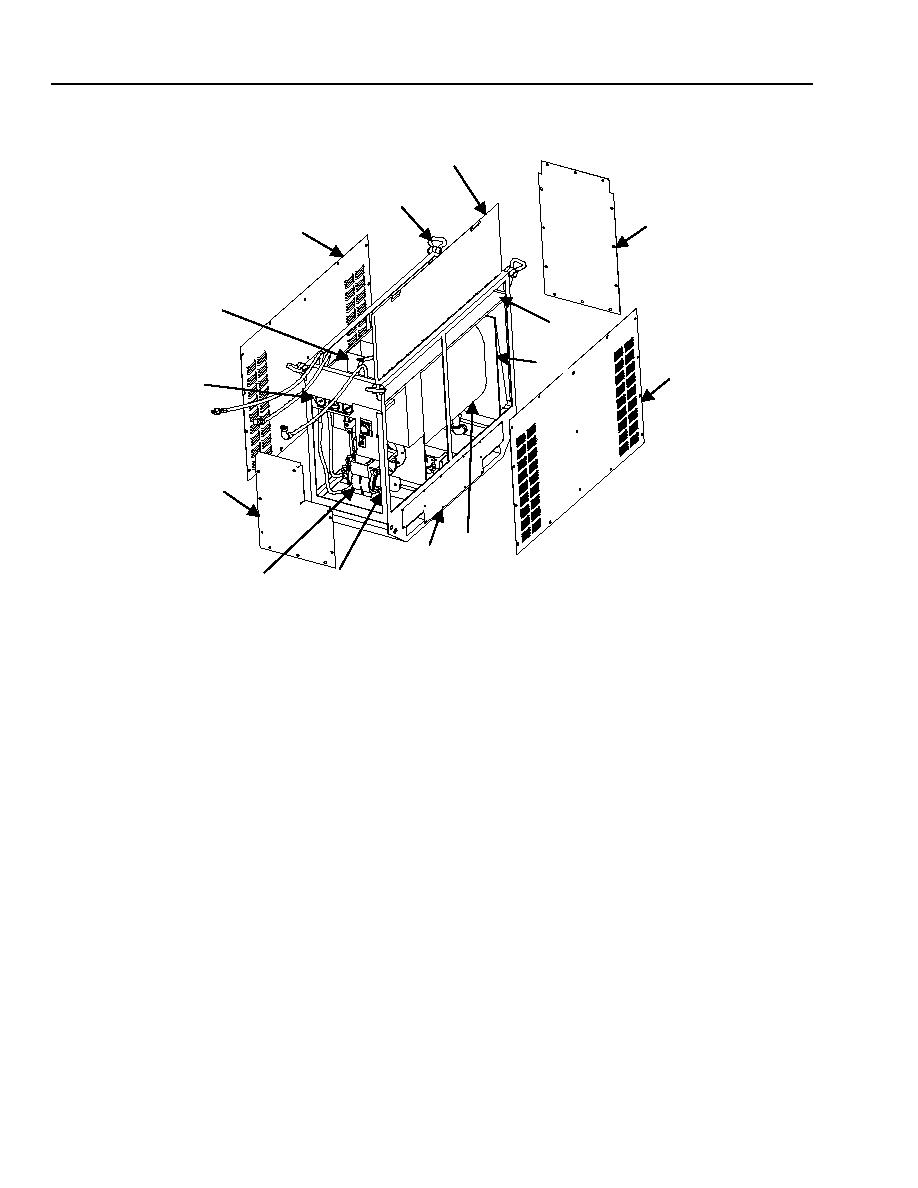
LIFTING EYE ASSEMBLY (1). Four lifting eye assemblies are used to pick up the water heater.
COVER PANELS (2). Fitted sheet-metal, quick-release removable panels protect the water heater from the elements. When
removed, the panels give access to components.
COVER (3). When heater is not used, the cover protects the water hoses, fuel hose assembly, power cable and keeps rain out of the
heater exhaust stack. When the heater is used, the cover must be open so exhaust gases can be vented through the top of the heater.
A canvas tool carrier is also attached inside of cover.
HOSE AND CABLE STORAGE COMPARTMENTS (4). Stores power cable assembly, fuel hose and filler opening assembly,
and water hose assembly.
REFRACTORY BOX (5). Evenly distributes heat from the burner through the boiler into the heat exchange tubing, where most of
the heat exchange takes place.
FRAME (6). A welded steel frame that serves as a mount for components of the water heater.
BOILER (7). A holding tank for heating water.
SKID ASSEMBLY (8). Provides a base for the water heater and a means to forklift the entire unit.
CONTROL BOX (9). Contains THERMOSTAT, HEATER ON/OFF switch, MAIN CIRCUIT BREAKER, and WATER
PRESSURE, FUEL PRESSURE and WATER TEMPERATURE gages.
BURNER ASSEMBLY (11). The burner assembly is an all-inclusive motor, fan, fuel pump, igniter, nozzle, and electrodes
contained on a housing, which atomizes and ignites the fuel mixture and then forces the burning fuel-air mixture through the boiler.
0002 00-4

