TM 3-4230-237-10
0002 00
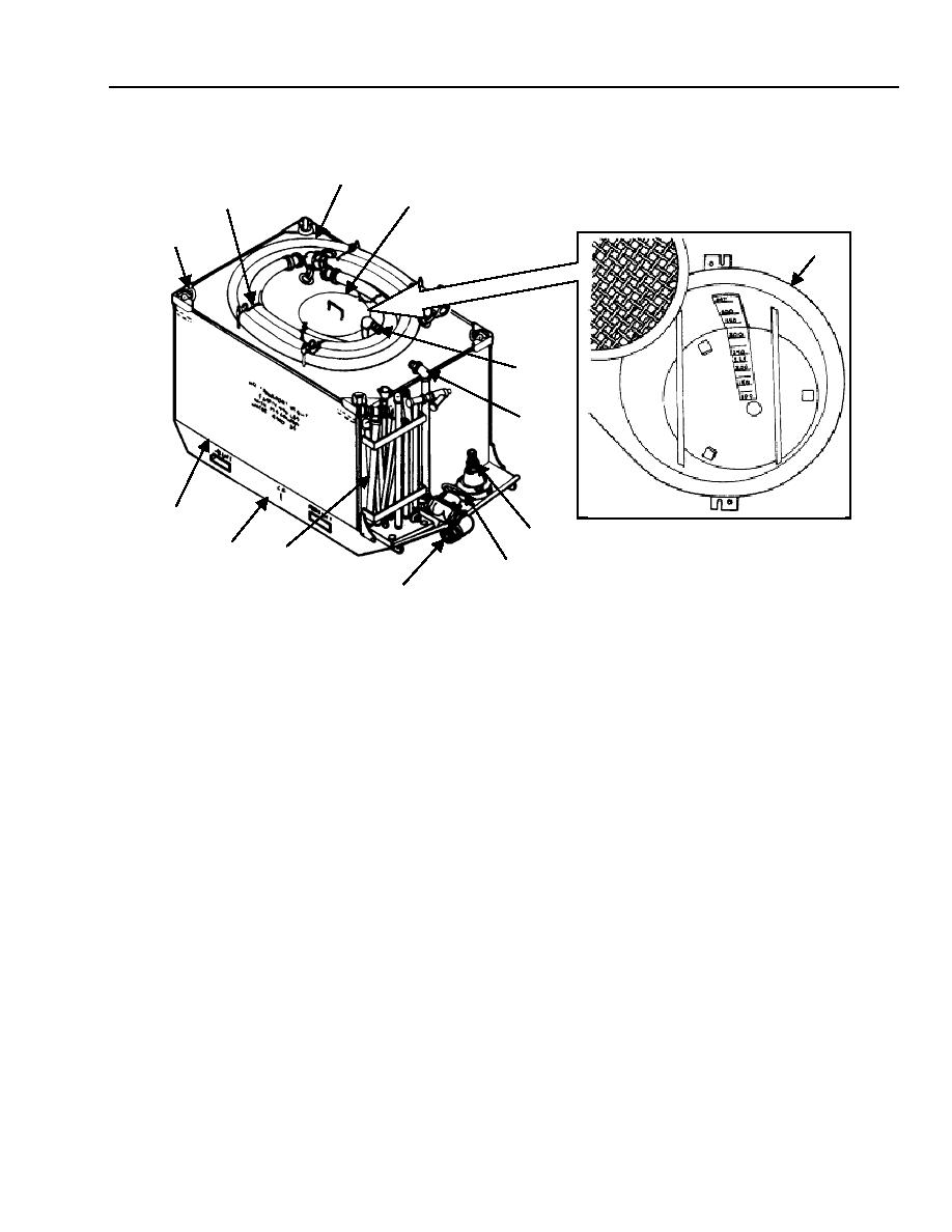
Tank Unit and Personnel Shower Assembly
3
2
4
1
4
5
6
12
7
11
10
8
9
LIFTING EYE ASSEMBLY (1). Four lifting eyes, on the top of the tank unit, are used to pick up the tank unit.
BRACKET CLAMP (2). Secures the suction hose on top of the tank unit when not in use.
SUCTION HOSE (3). Carries water from the tank unit through the tank drain valve or from a natural source to the pump unit.
HOPPER-BLENDER ASSEMBLY AND COVER (4). The hopper-blender assembly along with a fluid agitation system in the
tank blends decontaminating agent with water. The cover prevents foreign objects from entering the hopper-blender assembly.
BLENDER PIPE (5). Uses water from the pump unit to blend agents in the hopper-blender assembly.
AGITATOR PIPING (6). Uses water from the pump unit to agitate slurry in the tank unit assembly and is the passage for heated
water from the heater unit.
FOOT VALVE ASSEMBLY (7). Prevents objects from clogging the suction hose when water is being pumped from a natural
source. Clogs could damage the pump.
TANK DRAIN VALVE (8). Drains the tank unit.
HOSE ADAPTER (9). Provides for quick disconnect of the suction hose.
PERSONNEL SHOWER ASSEMBLY (10). Consists of pipes, couplings, and adapters. When connected, they form a field
shower to mass shower personnel in the field. When dismantled, it is stowed on the tank unit.
TANK UNIT SKID (11). Provides a base for the tank unit and provides a means to forklift tank unit.
TANK ASSEMBLY (12). Has a volume of 500 gallons and a maximum working capacity of approximately 447 gallons of water.
Working capacity for the tank with slurry mix is 317 gallons.
0002 00-3

