TM 5-4610-218-34
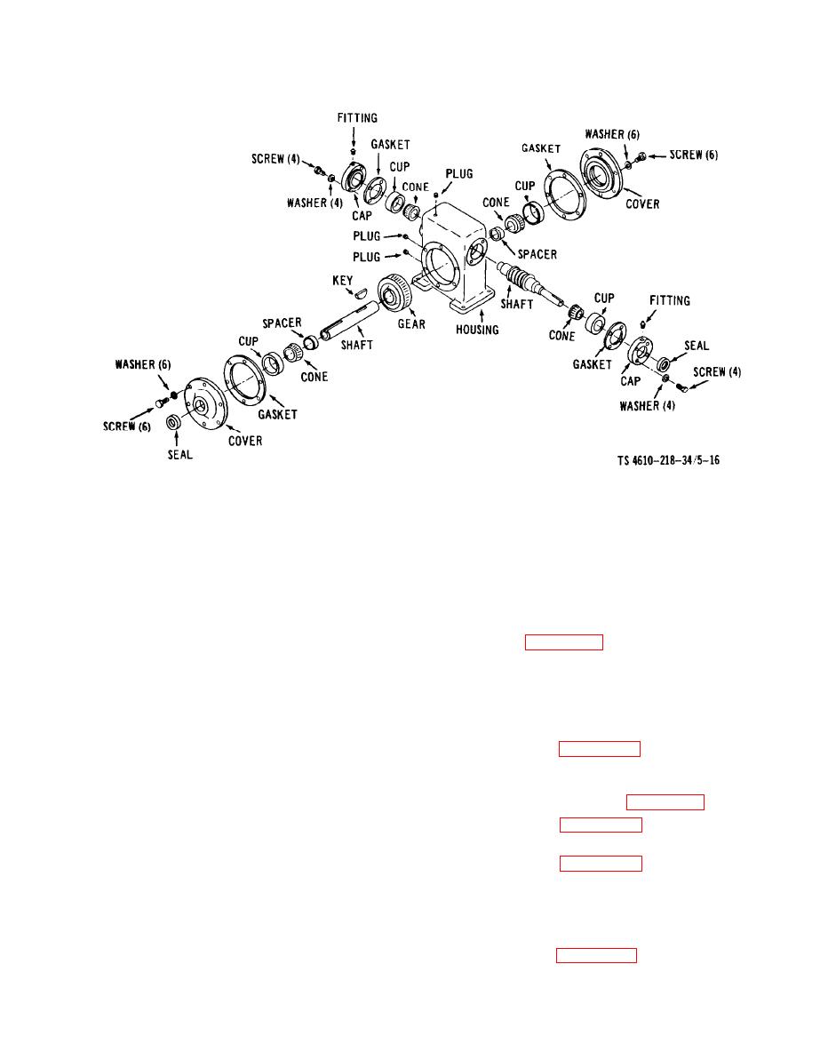
Figure 5-16. Slurry Feeder Speed Reducer, Disassembly and Reassembly
Section IV. CHEMICAL SOLUTION FEEDER
WARNING
(1) Remove the chemical solution feeder as
illustrated in figure 5-17.
Dry cleaning solvent, P-D-680,
used to clean parts, is potentially
(2) Remove the chemical solution feeder di-
dangerous. Avoid repeated and
aphragm pump bodies as illustrated in figure 5-
prolonged breathing of the vapors
17.
and skin contact with the liquid.
c. Disassembly.
Do not use near open flame or ex-
cessive heat. Use in a well-venti-
(1) Refer to figure 5-18 for disassembly of
lated area. The flash-point of P-D-
the drive arms.
680 is 100-138F (38-59C).
(2) Disassemble the solution feeder di-
aphragm pump as shown in figure 5-19.
5-4. Chemical Soultion Feeder.
(3) Refer to figure 5-20 for disassembly of
a. General. The chemical solution feeder con-
the lever arms and push rods.
sists of two diaphragm pumps operated by one
(4) Refer to figure 5-21 for disassembly of
electric motor through a gear reduction mech-
the junction box cover, receptacle, top housing,
anism which transmits the power to recip-
and lever arm shaft.
rocating mechanisms and priming levers. The
pumps operate at approximately 12 strokes per
(5) Remove the gear unit as shown in fig-
minute and each pump operates independently
ure 5-22.
of the other. The gear mechanism and motor are
encased in a cast housing and operate in oil.
gear unit.
b. Removal.
5-13


