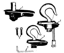
FIGURE 1. SUSPENSION ASSEMBLI[:S
1.
Lug type (single reeved adapter) for use with
Low Headroom Lodestar Trolley and Motor
Driven Trolley.
2.
Swivel hook type (double-reeved adapter).
3.
Rigid hook type (single-reeved adapter).
4.
Socket screw key.
5.
Socket head suspension screws.
(Do not order parts by these numbers. See parts list.)
ATTACHING LOAD CHAIN
Models E, H, R, RR, E-2, H-2, R-2 and RR-2
1.
Suspend the hoist from an adequate support.
2.
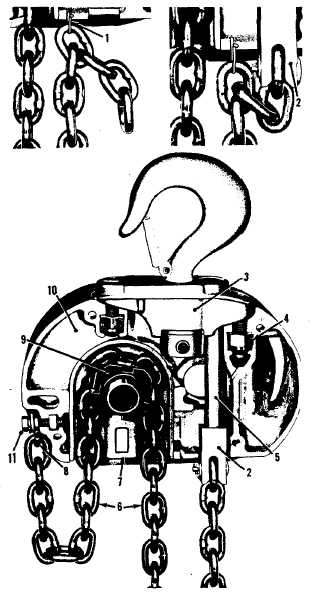
The hoist is shipped with the dead end of the
load chain temporarily positioned a few links
from the end by a light wire clip (1) as shown in
Figure 2. Do not remove this clip until the chain
is secured.
3.
Insert the last link of the load chain into dead
end block (2).
4.
Secure with the dead end pin, washer and cotter
pin furnished with the suspension.
5.
Remove clip (1) by inserting a screw driver
blade through a chain link and levering against
the bottom of hoist.
6.
Do not remove the ties from load chain.
Now, suspend the hoist from its permanent sup-
port or track system. If the hoist is to be hung
from a Low Headroom Lodestar Trolley or a Lode-
star Motor Driven Trolley, refer to the trolley in-
stallation instructions pages 7 and 8.
FIGURE 2. ATTACHING LOAD CHAIN
(Models E, H, E-2 and H-2 illustrated)
(Model R, RR, R-2 and RR-2 similar)
1. Wire clip
7.
Chain guide
2. Dead end block
8.
Loose end link
3. Suspension assembly
9.
Liftwheel
4. Suspension self-locking nut
10.
Gear housing
5. Dead end bolt
11. Loose end screw
6. Load chain
(Do not order parts by these numbers. See parts list.)
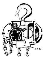
FIGURE 2A.
NOTE: Models R, R-2, RR and RR-2 are furnished with
a contact block (S-837). The dead end block (2)
passes thru the contact block and the contact block is
supported by the dead end pin.
FIGURE 2.
3


