POWER SUPPLY AND ELECTRICAL
CONNECTIONS
ALL HOISTS
The hoist should be connected to a branch
circuit which complies with the requirements of the
National Electrical Code and applicable local codes.
It is recommended, especially for a single phase
hoist with a one horsepower motor, that a line of
adequate capacity be run directly from the power supply
to the hoist to prevent having problems with low voltage
and circuit overloads.
For grounding of the hoist, the power cord
includes a grounding conductor (green wire). On a
standard single phase unit this cord is equipped with a
three-prong plug. Be sure that the receptacle opening
which receives the longest prong is properly grounded.
Furthermore, the suspension system on which the hoist
is mounted should also be permanently grounded.
Before connecting the hoist to the power supply,
check that the power to be used agrees with that shown
on hoist identification plate. In addition, for a three
phase, dual voltage unit, check the voltage shown on
the tag attached to power cord.
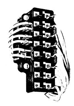
FIGURE 3
VOLTAGE CONVERSION TERMINAL BOARD
The nominal hoist voltage rating corresponding to the
voltage range given on hoist identification plate is:
SINGLE SPEED UNITS
RANGE
NOMINAL VOLTS
110-120
115
208-240
230
440-480
460
TWO SPEED UNITS
RANGE
NOMINAL VOLTS
208-230
230
440-460
460
THREE PHASE HOIST
Changing the voltage connections on a single
speed, three phase dual voltage unit, is easily done at
the conversion terminal board shown in Figure 3 located
in the hoist as shown in Figure 4.
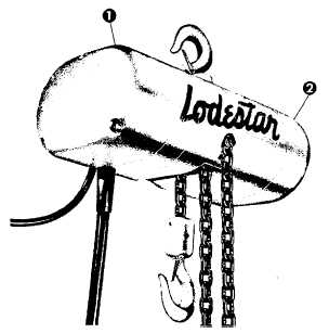
FIGURE 4
Voltage conversion terminal board is located under back
frame cover (1) for Models A thru H and under motor
housing cover (2) for Models J thru RR.
Limit switches and electric brake are located under back
frame cover for all hoists.
NOTE: The column of terminals on the left it marked
230 volts and the right-hand column is marked 460
volts.
To change the hoist voltage connections, simply shift
eight wires to the column of terminals marked.
4


