INSTALLATION
Locate the welder in a clean. dry place where there is free circulation
of air.
Be sure the voltage, phase and frequency of the input power is as
specified on the welder nameplate.
Dual and triple input voltage machines (230/460 and 220/380/440-50
hertz) are shipped with the motor leads disconnected but with the
higher voltage heater links in place and the lower voltage heater links
tied to the starter. Connect the motor leads and the appropriate heater
links as indicated on the instructions inside the starter cover.
Have a qualified electrician connect 3 phase AC power to the starter in
accordance with the National Electrical Code. all local codes and the
wiring diagram glued to the inside of the starter cover.
Recommended Input Wire, Ground Wire and Fuse Sizes
Based on National Electrical Code.
For 60 Hertz. 3 Phase Welders at 50s% Duty Cycle Rating
Input
Ampere
Copper Wire Size
Rating
Type 75° C in
(at200
Conduit
Fuse Size
Welder
Voltage
A.30V
3 Input
1 Ground
Ampers
Size
Input
Output)
Wires
Wires
(Super Lag)
230
32
#10
#10
60
250
460
16
#14
#14
30
575
12.8
#14
#14
25
The frame of the welder must be grounded. :A stud marked with the
symbol ¯ located on the starter mounting panel is provided for this
purpose. See the National Electrical Code for details on proper
grounding methods. (If an old machine does not have a grounding
stud, connect the grounding wire to an unpainted frame screw or bolt.)
Start the welder and check the direction of rotation. Proper direction
as shown by an arrow on the nameplate. On 3 phase machines the
direction of rotation can be changed by interchanging any two input
leads For two phase. 3 wire Input power. interchange the two outside
leads. Be sure the neutral wire is connected to the motor neutral.
which is the center terminal on the starter. For two phase. 4 wire input
power. interchange two leads in the same phase
NOTE: When changing the voltage connection for any machine
above code 4835 and bel6w code 3050. the heater links must be
changed. See page 7 to determine which heater links must be
installed. On machines with a code number between 3050 and
4835. the heater links do not have to be changed when changing
the voltage connection as long as the connection on the wiring
diagram inside the starter cover of these machines Is used
OPERATION
RECOMMENDED OUTPUT CABLES
Recommended Copper Cable Sizes at 30%
Duty Cycle
Machine
Cable Sizes of Combined Lengths of
Size
Electrode and Work Cable
in
0
100
150
200
Amperes
to 100
to 150
to 200
to 250'
180
4
3
2
1
250
3
2
1
1/0
ELECTRODE POLARITY
With the welder off connect the electrode cable to the DC negative or
DC positive stud as required for your particular application. Connect
the wo4k cable to the other stud.
DUTY CYCLE
These welders are NEMA rated for a 30% duty cycle. Duty cycle is
based on a 10 minute period. Therefore, they can be operated at a full
output (either 250 or 180 amps) for 3 minutes out of each 10 minute
period without over heating. At 50% duty cycle the output rating is 200
amps for the DC-250 & SAE-200J models or 145 amps for the DC-180
& SAE-152J models.
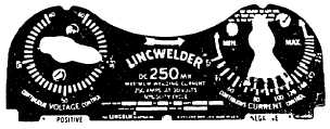
CONTROL OF WELDING CURRENT
Continuous Current Control
The continuous current control provides the major adjustment of
welding current to suit your particular applications The continuous
current control has a single dial calibrated in amperes. The control
handle has five pointers corresponding to the five major divisions on
the Continuous Voltage Control dial When the Continuous Voltage
Control dial is set on 55. for example. the approximate welding
current is indicated by the pointer marked 55 on the Current Control
handle.
Continuous Voltage Control
The Continuous Voltage Control is both the fine current control and
voltage control of your welder. With this control
-3-