MINOR REPAIRS
Control
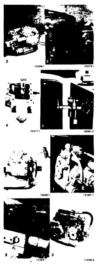
Removal
1.
Thoroughly clean external surfaces with steam or
clean solvent and blow dry.
2.
Remove the nine (9) cap screws (using 7/16"
wrench) and swing control away from housing.
CAUTION
Protect exposed surfaces and cavities
from damage and foreign material. Use
caution so that the rings and orifice plate
remain in place and do not fall into the
pump housing.
3.
Slip the pin on control linkage out of the link
attached to the swashplate and remove control.
The area is seated with both a gasket and three (3)
O-rings. The Variable Pressure Control does not
have a linkage to disengage.
Installation
4.
In preparation for installing the control, place a new
gasket on the housing. Insert the orifice plate and
three (3) O-rings into the control ports.
5.
Engage the pin on the control linkage in the mating
hole in the link attached to the swashplate. Use
caution so that the O-rings and orifice plate remain
in place and do not fall into the pump housing.
6.
Swing the control into place against the pump
housing. Install cap screws and torque to 10-11 ft.
lbs.
IMPORTANT: If the control being removed or replaced is
equipped with a .neutral start switch, accomplish the
"Neutral Start Switch Check procedure on page 33 following
control installation.
Pressure Override
Removal
1.
If a Pressure Override is mounted on top of the
Manual Displacement Control, it can be removed by
disconnecting the two (2) hose lines and removing
its six (6) cap screws (use 7 16" wrench). Lift the
Pressure Override from the control. This will
expose the three (3) remaining cap screws which
hold the Standard Displacement Control in place.
2.
The Pressure Override seals with four (4) O-rings.
Protect the exposed surfaces.
Installation
3.
With the four (4) O-rings in place. install the
Pressure Override on the control valve. Insert the
six (6) cap screws and torque to 10-1I1 ft. lbs.
Connect and tighten the two (2) hose fittings.
Page 31