CF 1, 2, 3, 4 RED INSULATED JUMPER. When in place the Light Module will signal common
fault at terminal 5. When clipped out the corresponding input signal will not signal the common
fault at terminal 5.
A 1, 2, 3, 4 YELLOW INSULATED JUMPER. When in place the horn will sound on that
corresponding signal input. When clipped out the horn will not sound when the corresponding
signal appears.
LAMP TEST JUMPER MARKED "T". When in place, terminal 27 is a B+ voltage for the lights
and horn. When clipped out a lamp test switch can be connected from terminal 27 to B- for
simultaneous test of all lamps connected to the module.
VOLTAGE JUMPER MARKED "V". When in place the Light Module will operate at 12 to 24
VDC. When clipped out the Light Module will operate at 32 VDC.
d.
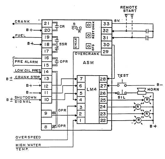
The Complete Engine Control System (Autostart A ght Module):
All connections shown in the diagram below are described in Articles A & B of this section.
PAGE 9