TM 10-4610-246-13
4.20
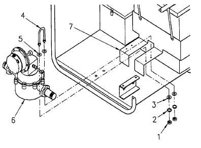
MAINTENANCE OF RATIO-FEEDER ASSEMBLY
This task covers:
a.
Removal
c.
Adjust
b.
Disassembly
INITIAL SETUP
Tools
Equipment Conditions
Tool Kit, General Mechanics
Suction valve removed (para 3.6).
(Item 1, App. B)
Discharge valve removed (para 3.7).
Parts/Materials
Inlet pipe assembly removed (para 4.16).
Lockwasher (TM 10-4610-246-23P)
Outlet pipe assembly removed (para 4.17).
a. Removal.
(1) Remove
nuts
(1,
Figure
4-9),
lockwashers (2), flat washers (3), clamp
(4), and flat washers (5) securing ratio-
feeder assembly (6) to frame assembly
(7).
(2) Remove ratio-feeder assembly (6) from
frame assembly (7).
b. Installation.
(1) Position ratio-feeder assembly (6) on
frame assembly (7).
(2) Secure ratio-feeder assembly (6) with
flat washers (5), clamps (4), flat washers
(3), new lockwashers (2), and nuts (1).
c. Adjust.
NOTE
Figure 4-9. Ratio-Feeder Assembly
Ratio-feeder assembly must be adjusted
while unit is in operation. Turn stroke
adjusting knob only during turning stroke.
(1) Turn ratio-feeder assembly completely
off by turning stroke adjusting knob (1,
Figure 4-10) clockwise as far as
possible, while pump is in operation.
4-18