ARMY TM 10-4610-309-14
MARINE CORPS TM10802A-14/1
0009 00
TACTICAL WATER PURIFICATION SYSTEM (TWPS)
PREPARATION FOR USE AND INSTALLATION INSTRUCTIONS
COLD WEATHER SET-UP OPERATION UNDER UNUSUAL CONDITIONS
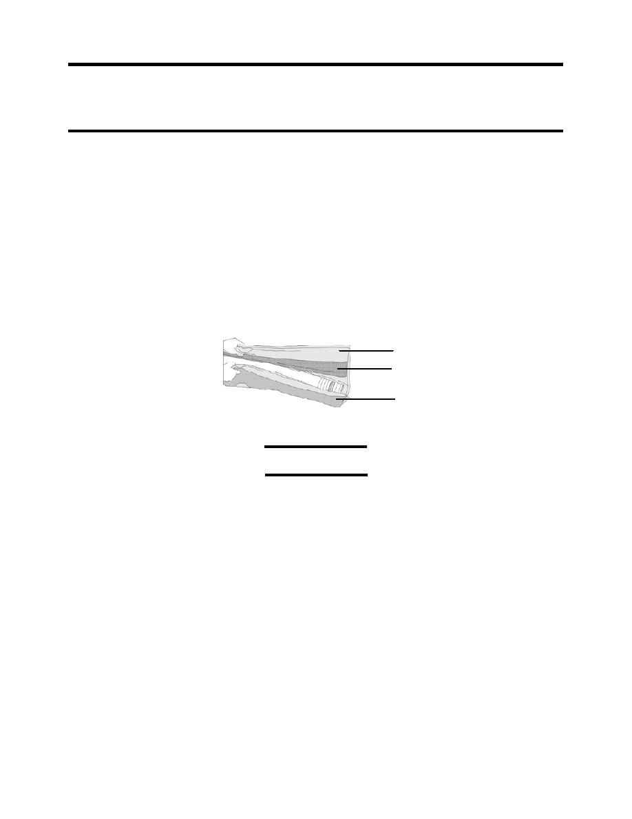
2. Install hose heating blankets as follows (see Figure 16):
NOTE
There are no hose heating blankets for the hoses on the OISS assembly.
a. Refer to Table 6 below for a listing of the hoses that get heating blankets and the pump
skid junction box to which each heating blanket power cable is connected.
b. Roll out the hose heating blanket and place the outside surface down next to the hose.
c. Lift the hose and slide the heating blanket under the hose.
d. Wrap the heating blanket around the hose and secure with the hook and loop strips.
e. When two or more heating blankets are used on hose combinations, join the blankets at
the seams so that they overlap the hose couplings.
f. The straps that are removed from the rolled up blankets can be strapped around the
installed blankets at the ends.
g. Heating blankets must be positioned over the couplings at the end of the hose.
HOSE HEATING BLANKET
HOOK AND LOOP STRIP
HOOK AND LOOP STRIP
Figure 16. Hose Heating Blanket Installation.
CAUTION
Connector damage or poor electrical connection. Use the fine brush from the tool
box to clean dust and sand out of connectors, terminals and dust caps before
making or capping a connection. Install the dust cap provided with connectors
and terminals whenever a connector is disconnected from its terminal. Failure to
observe this caution may result in connector damage or a poor electrical
connection.
h. Clean the connectors and connect the hose heating blanket power cables to the hose
heater terminals on the pump skid junction boxes as identified in Table 6 Figure 17 for
the P-1 to P-2 raw water system configuration and Table 7 Figure 18 for the P-2 only
configuration. Do NOT connect the pump skid power cables to the TWPS PDP (power
distribution panel) at this time.
i. If the Diesel-Driven Pump P-1 is used, the heating blanket power cables will be
connected to the P-1 junction box later.
NOTE
Lay out the hose blankets connecting to the Diesel-Driven Pump P-1 (if to be used)
using the location marker as a guide. The P-1 pump will be deployed and the
installation will be completed just before establishing raw water flow.
0009 00-22


