ARMY TM 10-4610-309-14
MARINE CORPS TM10802A-14/1
0009 00
TACTICAL WATER PURIFICATION SYSTEM (TWPS)
PREPARATION FOR USE AND INSTALLATION INSTRUCTIONS
COLD WEATHER SET-UP OPERATION UNDER UNUSUAL CONDITIONS
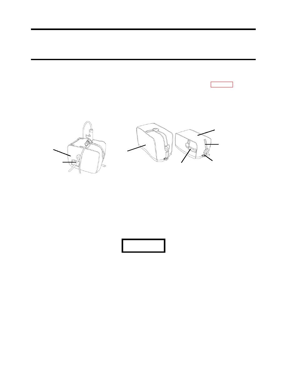
5. Install pump skid insulating covers on pump skids P-1 (if used), P-2, and P-3 as follows (see
Figure 20):
a. If the P-1 pump is used, perform P-1 pump PMCS in accordance with WP 0038.
c. Place the cover over the pump skid.
d. For P-2 and P-3 pumps, run the power cable out around the cover at the bottom
e. Secure the buckle to draw the bottom tight around the skid.
f. Attach the hook and loop strips on the flaps at the hose inlet and outlet.
P-3
HOOK AND
P-1
LOOP STRIP
P-2
EXHAUST
BUCKLE
HOOK AND
HOSE
LOOP STRIP
Figure 20. Pump Skid Insulating Cover Installation.
WASTE OUTLET CONNECTIONS
Install the waste outlet connection as follows (see Figure 21):
1. Collect the following adaptor and hoses.
a. One 4 in. x 5 ft., red-banded suction hose.
b. Waste out Adaptor A-09.
c. One 6 in. x 50 ft., red-banded discharge hose.
2. Connect the hoses and adaptor as follows:
WARNING
Under certain conditions, air may be pushed out of the waste hose causing the end
to whip. Do not make any waste hose connections while the TWPS is operating.
Stand clear of the waste hose end by at least 20 ft. while the TWPS is operating.
Failure to observe this warning may result in serious injury.
a. Insert the 4 in. x 5 ft., red-banded suction hose through the sleeve in the winter cover or
fabric wall and connect it to the waste outlet at the TWPS.
b. Connect Adaptor A-09 to the end of the 4 x 5, red-banded suction hose.
c. Connect the 6 in. x 50 ft., red-banded discharge hose to the other end of Adaptor A-09.
d. Place the other end of the waste hose so that it discharges at least 50 ft. downstream
from the raw water inlet. Remove any sharp kinks or bends in the hose.
0009 00-25


