ARMY TM 10-4610-309-14
MARINE CORPS TM 10802A-14/1
TACTICAL WATER PURIFICATION SYSTEM (TWPS)
0016 00
OPERATOR INSTRUCTIONS
MAINTAINING NORMAL OPERATION UNDER USUAL CONDITIONS
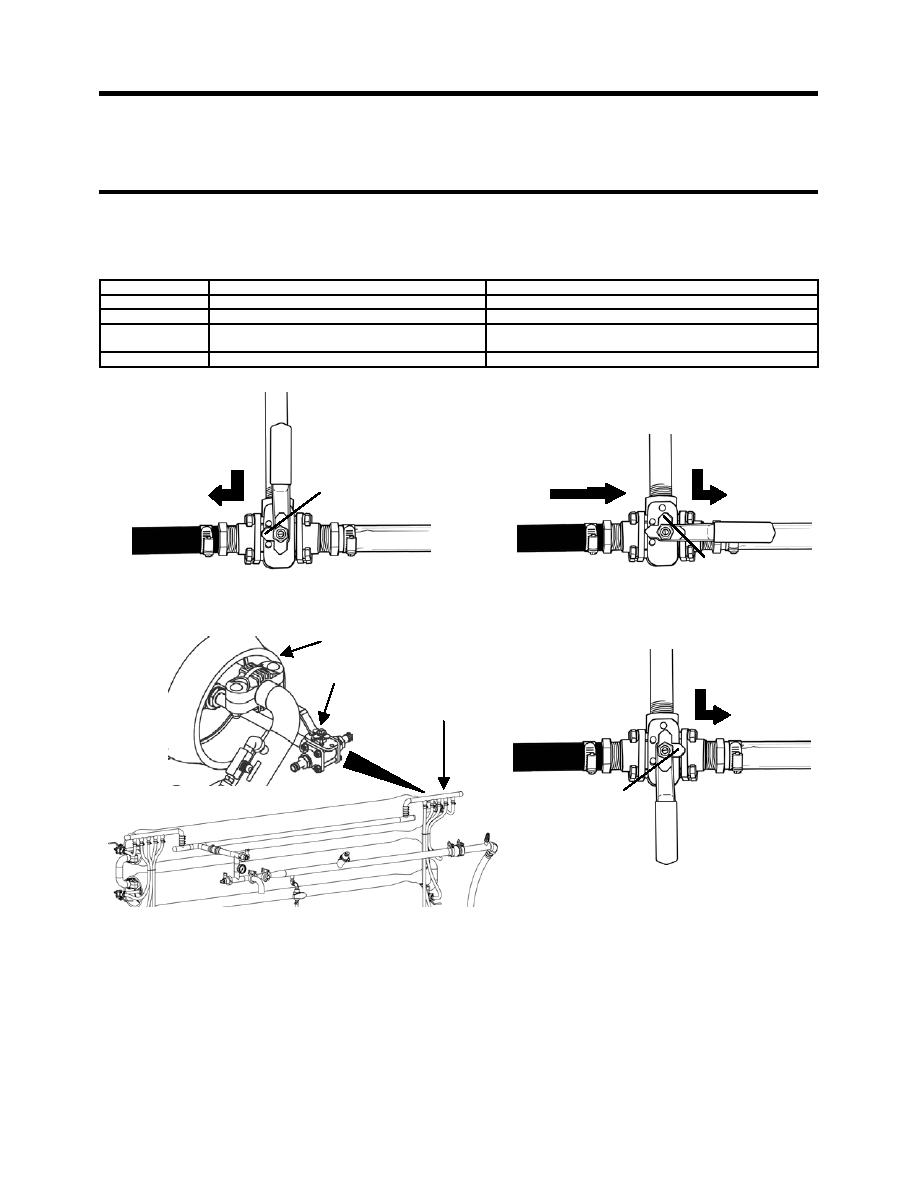
The RO vessels are designed so that the product water from each element is discharged separately to
the Product Manifold through a 3-way valve (see Figure 7). The 3-way valve can be positioned one of the
following three ways:
Position Name
Physical Positioning
Direction of Water Flow
Normal Position
Middle pointer points toward black product hose.
From RO vessel to distribution system.
Drain Position
Middle pointer points toward RO Vessel.
From RO vessel and black product hose (and product
manifold) to clear drain hose.
Sample Position
Middle pointer points toward clear drain hose.
To clear drain hose.
FROM RO VESSEL
FROM RO VESSEL
TO
FROM BLACK PRODUCT HOSE
TO
DISTRIBUTION SYSTEM
TO
CLEAR DRAIN HOSE
CLEAR DRAIN HOSE
MIDDLE POINTER
MIDDLE POINTER
VALVE NORMAL POSITION
VALVE DRAIN POSITION
RO VESSEL
FROM RO VESSEL
TO
3-WAY VALVE
CLEAR DRAIN HOSE
PRODUCT MANIFOLD
MIDDLE POINTER
VALVE SAMPLE POSITION
Figure 7. RO Vessel 3-Way Valve Positions.
Perform the RO element product flow and conductivity tests as follows:
1. Collect the following items:
a. RO Element Product Flow Tester
b. (MC-TWPS) Portable TDS Meter Kit with TDS Meter and Calibration Solutions
c. (A-TWPS) WQAS-P with TDS Meter and Calibration Solutions
0016 00-15


