ARMY TM 10-4610-309-14
MARINE CORPS TM 10802A-14/1
0066 00
TACTICAL WATER PURIFICATION SYSTEM (TWPS)
UNIT MAINTENANCE PROCEDURES
GENERAL MAINTENANCE
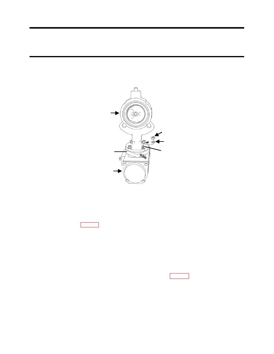
g. Set the valve over the threaded studs and onto the limit stop body with the valve oriented
as shown in Figure 12.
h. Secure the valve to the limit stop body and actuator using the four star washers and four
nuts that were supplied with the limit stop assembly.
VALVE
NUT
STAR WASHER
LIMIT STOP BODY
THREADED STUD
ACTUATOR
Figure 12. Valve V-113 Installation on the Limit Stop.
5. Install the butterfly valve assembly onto the TWPS. Refer to the Butterfly Valve Replacement
procedures.
6. Set the limit stop stop-screws as follows (see Figure 13):
a. Perform the diagnostic self-test procedures through V-113 Valve Cycle test step # 6.
Refer to WP 013.
b. Check that the triangle-shaped position indicator on the V-113 actuator is pointing
straight up, indicating that the valve is fully open.
c. Back the jam nut on the top stop-screw to the end of the stop-screw.
d. Screw the top stop-screw into the limit stop body so that approximately 3/8-in of stop
screw is sticking out of the limit stop body.
e. Tighten the jam nut onto the limit stop body.
f. Unscrew the bottom stop-screw out of the limit stop body, then screw it back in about a
half inch.
g. Tighten the jam nut onto the limit stop body.
h. Complete the diagnostic self-test procedure. Refer to WP 013.
i. Check that the triangle-shaped position indicator on the V-113 actuator is pointing about
45 degrees to the right of the fully open, straight up position.
j. If the triangle-shaped position indicator is not at 45 degrees, repeat the diagnostic self-
test procedure stopping at step # 6. Readjust the top stop-screw by turning in to increase
the angle or turning out to decrease the angle
k. Complete the diagnostic self-test procedure and check that the position indicator is at 45
degrees. Repeat the adjusting procedure if necessary until the position indicator is at 45
degrees at the completion of the self-test procedure.
0066 00-13


