TM 10-4610-310-14
0004 00
REVERSE OSMOSIS ELEMENT MODULE
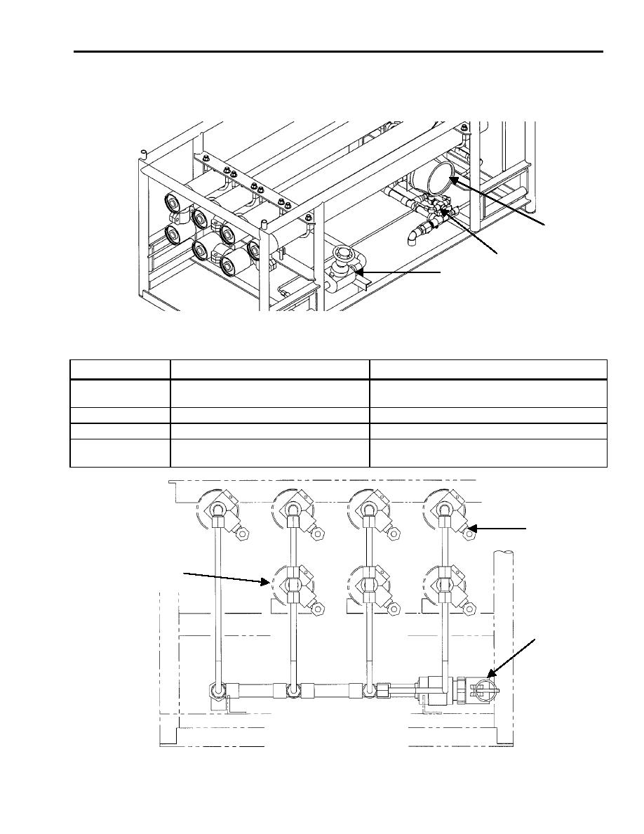
Controls and indicators on the Reverse Osmosis (RO) module are identified on Figure 11, Figure 12, and
described in Table .
1
3
2
Figure 11. Reverse Osmosis Element Module.
Table 6. Reverse Osmosis Element Module Controls and Indicators.
KEY
CONTROL OR INDICATOR
FUNCTION
1
Differential pressure gauge, 0 to 1500
Indicates the differential pressure in the RO
psi, DP-2
element module
2
Needle valve, 0.5-inch, v11
Control reject valve
3
3-way ball valve, 0.25-inch, V50
Use as a differential pressure diverter valve
4
3-way ball valve, 0.375-inch, V30
Used to drain and take samples of the water in
through V36
the pressure vessels
4 (7 PLACES)
PRESSURE
VESSEL
(7 PLACES)
PERMEATE
OUTLET
Figure 12. Sampling Ball Valves and Pressure Vessel Assemblies.


