TM 10-4610-310-14
0004 00
CHEMICAL INJECTION/CLEANING MODULE
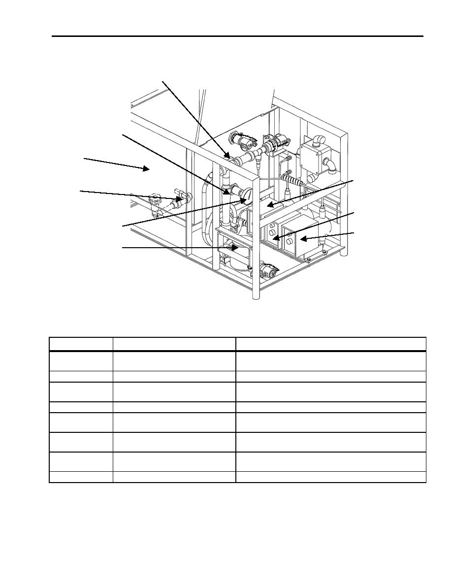
Controls and indicators on the chemical injection/cleaning module are identified on Figure 13, Figure 12, and
described in Table .
1
2
CLEANNG
TANK
7
8
6
3
5
4
Figure 13. Chemical Injection/Cleaning Module.
Table 7. Chemical Injection/Cleaning Module Controls and Indicators.
KEY
CONTROLS AND INDICATORS
FUNCTION
1
Diverter ball valve, V13
Directs flow of product water to the product water outlet
or to 6-foot hose to fill
2
Flow meter, 0 to 3 GPM, FI-2
Determines the flow of the product water
3
Temperature gauge, TI-2
Indicates the temperature of the cleaning solution in the
cleaning tank T4
4
Flow totalizer, FQ-2
Cumulates total flow of product water in gallons
5
Chemical injection pump, P5
Injects antiscalant into inlet water into high-pressure
pump module. See Table .
6
Chemical injection pump, P6
Injects coagulant into raw water before the settling tank
T1. See Table .
7
Chemical injection pump, P7
Injects hypochlorite into product water just before going
into the product tank T3. See Table .
8*
Clean out valve, V14
Drains all solutions from cleaning tank T4
*item is located on the bottom of the cleaning tank.
Chemical Injection Pump
There are three chemical injection pumps supply chemicals to the raw water or product water during operation.
The pumps are manually adjusted to provide stroke and speed for the injection of appropriate chemical to the
desired location. Refer to Figure 14 for an illustration of the pump and Table for a description.


