TM 10-4610-310-14
0009 00
STARTUP CONTINUED
4
3
2
1
5
7
9
13
8
10
15
17
6
11
12
16
14
18
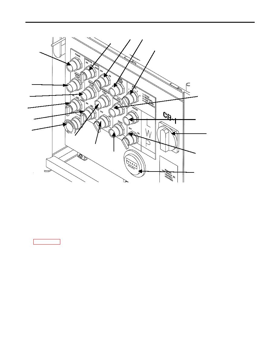
Figure 21. Control Module.
6. Disconnect the fabric hose (green) from the inlet of the UF module so the hose can be flushed out. The
hose will need to be reconnected to the UF module after being flushed for 5-10 seconds.
7. Place the BOOSTER PUMP switch (8) and BACKWASH PUMP selector switch (10) in the AUTO position
on the control module. Green pilot light (7) will light up. Green pilot light (9) will only light up during
backwash cycle. See Figure 21 for location of switches.
8. It may be necessary to prime the booster pump. If so follow the steps to priming the raw water pump. See
9. The pump will start drawing the water from the settling tank. Allow the fabric hose (green) to be flushed out
for 5-10 seconds by disconnecting it momentarily. Ensure that the camlock fittings are thoroughly cleaned
and reconnect the hose to the inlet of the UF module.
10. Prime the backwash pump during initial startup.
a. Make sure that the filtrate tank on the UF module is at least half full.
b. Disconnect the backwash pump discharge hose (yellow) from UF module backwash inlet.
c.
Place BACKWASH PUMP selector switch (10) in the ON position on the control module.
d. Allow the hose to be flushed for 5 seconds and ensure that the camlock fittings are thoroughly cleaned.
e. Reconnect the hose to the backwash inlet on the UF module.
f.
Place the backwash pump switch in the AUTO position.
15. Filtrate tank will begin to fill as indicated on the flow indicator. See Figure 7.
16. Ensure the filtrate tank on the UF module is completely full before continuing.


