TM 10-4610-310-14
OPERATOR INSTRUCTIONS
LIGHTWEIGHT WATER PURIFIER
OPERATION UNDER USUAL CONDITIONS
SHUTDOWN/PRESERVATION PROCEDURES
INITIAL SETUP
Tools
Equipment Condition Required
Wrench, adjustable
LWP running in normal configuration
Product tank at least 1/3 full
Material/Parts
Protective Clothing (Goggles, gloves, apron)
Sodium Metabisulfite (M323)
GENERAL
This work package contains information and operator instructions to be followed for the product flush, short-term
shutdown (less than 96 hours), long-term shutdown with preservation (more than 96 hours), and for an
emergency shutdown of the Lightweight Water Purifier (LWP).
A product flush is performed when system is shutdown for more than 4 hours.
A short term shutdown is performed when more than 4 hours and less than 96 hours and/or LWP is being moved
to another location or exposure to freezing temperatures of 32F or less is expected within 24 hours. This is
basically a product flush followed by draining.
A long-term shutdown is performed when the LWP operation will be suspended for more than 96 hours. The
LWP is thoroughly flushed with dechlorinated product water, preserved and drained.
SHUTDOWN
1. Open reject valve V11 on Reverse Osmosis (RO) element module completely.
2. Push in the throttle cable all the way on the diesel engine and shut it down. See WP 0009 00.
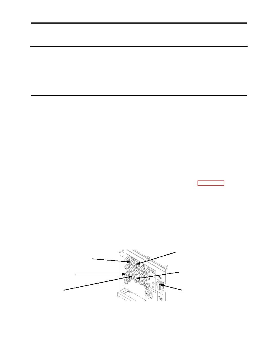
3. Place the CHEMICAL PUMPS switch on the control module to the OFF position.
4. Place the RAW WATER PUMP switch on the control module to the OFF position.
5. Ensure that the DISTRIBUTION PUMP switch on the control module to the OFF position.
6. Place the BOOSTER PUMP switch on the control module to the OFF position.
7. Place the BACKWASH PUMP switch on the control module to the OFF position.
8. Place the CIRCUIT BREAKER switch on the control module to the OFF position.
9. All the lights on the control panel should be off. Close the inlet valve on the settling tank and product tank
to prevent inadvertent draining. Shut down the 3kW TQG per TM 9-6115-639-13.
CHEMICAL
RAW WATER
PUMPS
PUMP SWITCH
SWITCH
DISTRIBUTION
BOOSTER
PUMP SWITCH
PUMP
SWITCH
BACKWASH
CIRCUIT
PUMP
BREAKER
SWITCH
CB1
Figure 1. Control Module.


