TM 10-4610-310-14
0130 00
DISASSEMBLY - continued
Pump
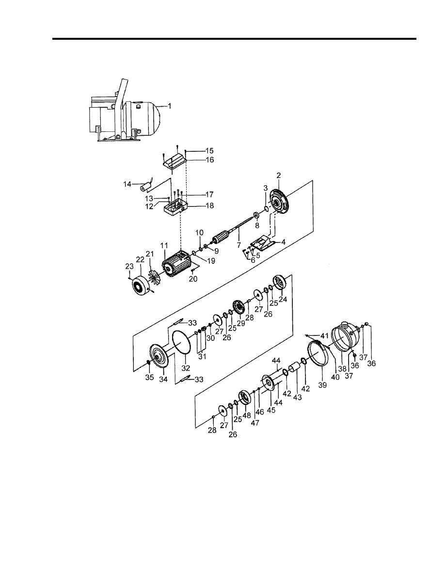
Figure 4. Service Pump (Exploded View)
1. Remove intermediate chamber (24), impeller, (27), and spacing pipe (28) from rotor (7) shaft.
2. Remove top intermediate chamber (29), impeller (27), and spacing pipe (28) from rotor (7) shaft.
3. Remove top intermediate chamber (29) by inserting a screwdriver in a slot on the side of top intermediate
chamber (29).
4. Remove top intermediate chamber (29) from the rotor (7) shaft by pushing the shaft of the screwdriver back
against cover plate (34).


