
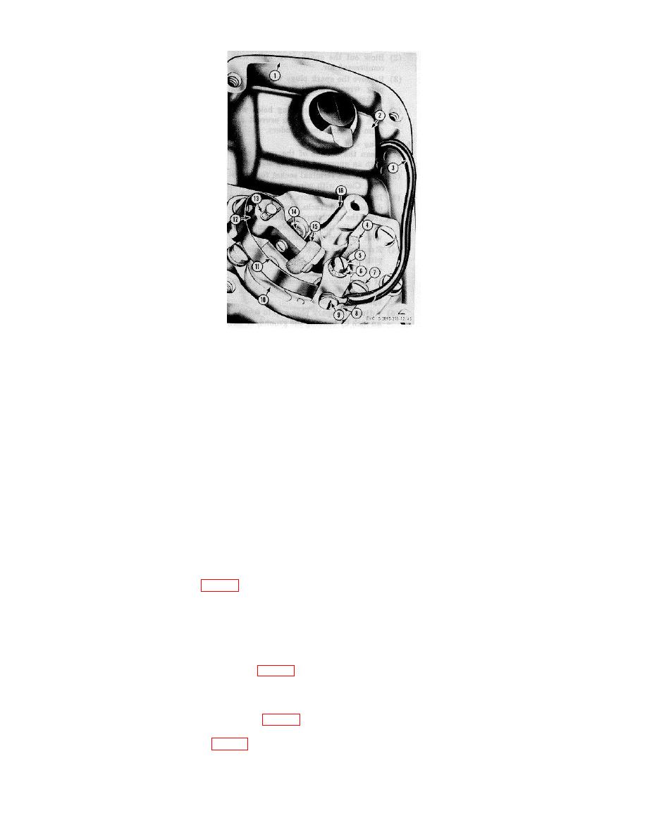
1
Housing
5
Screw
9 Screw
13
Pivot snapring
2
Coil
6
Lockwasher
10 Plate
14
Contact
3
Ground Wire
7
Screw
11 Screw
15
Feltwick
4
Camwick
8
Plate
12 Breaker arm
16
Rotor shaft
Figure 28. Magneto adjustment
and is driven off the timing gears at camshaft speed. The magneto is enclosed in a metal frame, cap, and end
cover. Threaded cable outlets are provided for connection to the spark plug lead shielding. All the interior
metal is interconnected and grounded to provide radio shielding. The magneto armature is a one-piece
magneto rotor that rotates between the pole pieces of a laminated iron frame causing an induced current to
flow in the primary circuit of the coil, during the time the contact points are closed. When the points open, the
primary circuit is broken, instantly collapsing the field and inducing the secondary circuit of the coil
to produce the intense ignition spark for startings. An impulse coupling is provided which makes possible the
production of a spark at cranking speed equal to that produced when the engine is running. The impulse
consists of a hub and shell connected by a torsion type spring. Through this device, the magneto armature is
held back while the engine is turned over to just past top dead center, at which instant the pawls of the coupling
are released by the pawl stop pin, causing the power coil spring to snap the magneto armature forward at high
speed. This produces an intense spark, automatically retarded to prevent kick-backs. When the engine starts,
the pawls are disengaged by centrifugal action of the drive gear,
causing the coupling to act as a direct drive.
b. Adjustment.
(1) Remove screw (8, fig. 18) and lockwasher securing the magneto stop switch wire.
(2) Remove the four connectors (20) securing the spark plug cables and disconnect the cables, tagging
each so they can be replaced in their proper sockets in the magneto.
(3) Remove the four screws (11) and lockwashers securing the end cover (12) and remove the end
cover and gasket (13).
(4) Rotate the crankshaft with the starting crank until the breaker arm is riding on the high spot of the
camshaft and the breaker points are wide open.
(5) Loosen the locking screws (7, fig. 28) on the contact plate so that the plate is movable.
(6) Insert the end of a small screwdriver into the adjusting slot at the bottom of the contact plate (10)
and open or close the breaker points by moving the contact plate until the clearance is .015
checked with a feeler gage.
(7) Tighten the locking screws (7 and 11) and recheck the breaker point gap (14) to make sure it has
not changed.
(8) Position gasket (13, fig. 18) and end cover (12) on the magneto and secure with four lockwashers
and screws (11).
AGO 6871A
50