TM 5-4610-218-34
Sludge concentrator tank. . . . . . . . . . . . . . . . . . . . . . . . . . . . . . . . . . . . . . . . . .. . . . . . . . . . . . . . . 180 gal. (680.4 L)
Water treatment time at 1500 gph . . . . . . . . . . . . . . . . . . . . . . . . . . . . . . . . . . . . . . . . . . . . . . . . . 18.6 min.
Chemical solution tanks (each) . . . . . . . . . . . . . . . . . . . . . . . . . . .. . . . . . . . . . . . . 5 gal. (18.9 L)
Chemical solution feeder gear case . . . . . . . . . . . . . . . . . . . . . . . .. . . . . . . . 1 1/4 qts. (1.18 L)
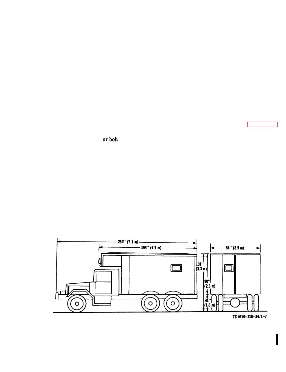
shows the dimension and clearance for the
Torque
Size nut
Size nut
water purification unit.
(ft.lb)
(ft.-lb.)
or bolt
f. Wiring Identification Plate, Van Body. FO
1 shows the wiring diagram for the van body.
90-100
9/16-12
7-9
1/4-20
g. Wiring Identification Plate, Water Puri-
107-117
1/4-28
9/16-18
8-10
fication Unit. FO 2 shows the wiring diagram
for the water purification unit electrical system.
137-147
6/16-18
5/8-11
13-17
168-178
5/16-24
5/8-18
15-19
240-250
3/8-16
3/410
30-35
Figure 1-7. Dimension and Clearance
1-17/(1-18 blank)
Change 2


