TM 5-4610-223-12
TS 4610-223-12/3-21
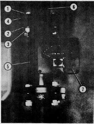
1.
Capscrew, hex hd (8 reqd)
4.
Flange (2 reqd)
2.
Washer (8 reqd)
5.
Raw water line
3.
Nut, hex (8 reqd)
6.
Raw water piping
7.
Flow indicator
Figure 3-21. Raw Water Flow Indicator.
3-41. CHEMICAL SLURRY FEEDER ASSEMBLY.
a.
General. The chemical slurry feeder consists essentially of an aluminum tank (1, fig. 2-11) divided into two
equal watertight compartments. The two compartments are covered with one hinged cover. Each compartment has four
agitators with two measuring cups attached to diametrically opposite agitator a clear-plastic window, drain outlets,
collecting funnel, filling agitators operate connections and rate-of-discharge controller. The chemical slurry feeder
agitators operate from a common shaft and rotated vertically. Each compartment functions as a separated unit
permitting two different chemical solutions to be fed at the same time. The chemical slurry feeder tank (1) supplies
pulverized limestone slurry (coagulated aid) to the erdlator tank and diatomite slurry to the diatomite dilution tank (3).
3-54