TM 5-4610-223-12
1.
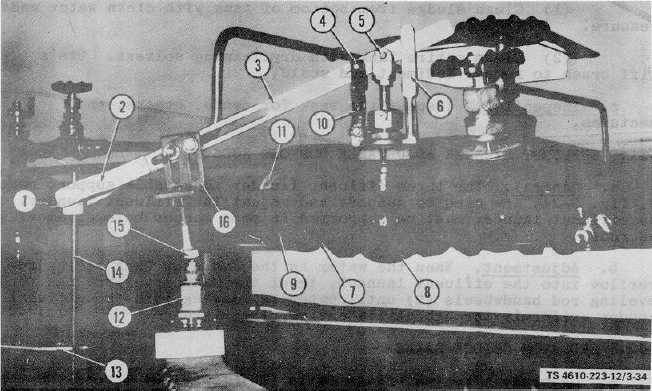
Thumbscrew, 1/4-20 x 1/2 in.
10.
Connecting link
2.
Float rod connector
11.
Nipple, pipe, 1 1/2 x
3.
Float lever
2 1/2 in.
4.
Lever pin (3 reqd)
12.
Sensitive switch
5.
Pin, cotter, 1/16 x 1/2
13.
Float rod bracket
in. (6 reqd)
14.
Float rod
6.
Lifter
15.
Screw, cap, hex hd,
7.
Nipple, pipe, 1 1/2 x 1 3/4
5/8-18 x 2 1/2 in.
in. (2 reqd)
16.
Bracket
8.
Valve body, 1 1/2 in.
9.
Elbow, w/union, female,
1 1/4 in., 90 degree
Figure 3-34. Low Water Alarm Float and Valve Assembly.
b.
Cleaning. Clean valve with drycleaning solvent.
c.
Inspection. Inspect valve for cracks and damaged threads. Check the valve rod to see if it will move freely and
turn the valve body.
d.
Adjust. Adjust the float lever (3, fig. 3-34) of float valve FV-18 (8) if the float valve does not completely close or
when the water level in the wet well tank is 10 inches (25.4 cm) below the top of the tank. Loosen the thumbscrew (1)
securing the float rod (14) to the float lever and move the lever up or down until the valve closes. Tighten thumbscrew.
3-76