TM 5-4610-223-12
1.
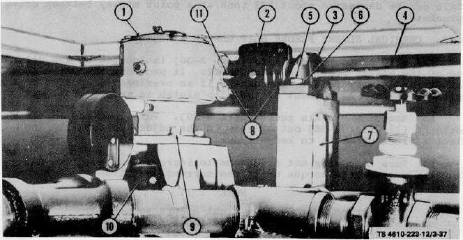
Speed reducer, gear assembly
7.
Nut, hex 3/8-16 (4 reqd)
2.
Flexible coupling
hidden
3.
Pillow block bearing
8.
Bearing (2 reqd)
4.
Erdlator agitator shaft
9.
Capscrew, hex 3/8-16 x 1 in.
5.
Capscrew, hex 3/8-16 x 3/4
(4 reqd)
in. (4 reqd)
10.
Flexible coupling
6.
Lockwasher, 3/8 in. (4 reqd)
11.
Speed reducer input shaft
Figure 3-37. Erdlator Agitator Drive Shaft Assembly.
(2)
Inspect pillow blocks for cracks.
(3)
Inspect all threaded parts for damaged threads.
(4)
Inspect for worn keys and keyways.
3-61. ERDLATOR AGITATOR SPEED REDUCER.
a.
General. The speed reducer (1, fig. 3-37) is located on top of the erdlator tank on the bridge rails above the
erdlator agitator. It reduces speed from the electric motor to the erdlator agitator.
3-82