Engine Disassembly and Assembly
Cylinder Head Assembly And
Spacer Plate
15.
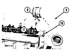
Remove bolt (11). Put lifting bracket (8) and
mounting bracket and pipe assembly (9) in position, and
install bolts (10). Install bolt (11), and tighten it to a
torque of 43 + 7 Nom (32 ± 5 Ib. ft. ).
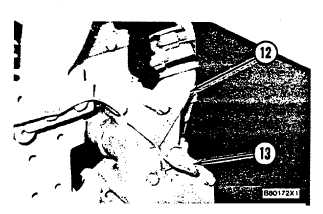
16. Put the gaskets and elbow (12) in position and
install the bolts that hold them. Tighten the hose clamp
on the back side of the elbow.
17. Install temperature sending unit (13) in the elbow.
END BY:
a.
install valve cover
b.
install exhaust manifold
c.
install air cleaner group
d.
install aftercooler
Valve Lifters
Remove And Install Valve Lifters 1209-010
START BY:
a. remove cylinder head assembly and spacer plate
1.
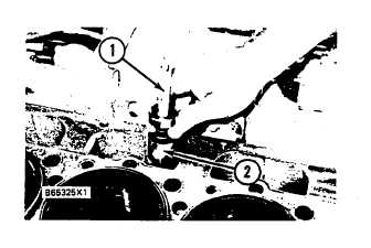
Use a magnet (1) to remove valve lifters (2). Put
identification marks on lifters for installation purposes.
2.
Check the diameter of the valve lifter. The
diameter of the valve lifter (new) must be 33. 287 + 1.
311 mm (1. 3105 i . 0516 in. ). The bore in the block
for new valve lifters must be 33. 388 + 0. 025 mm (1.
3145 + . 0010 in. ). The maximum permissible
clearance between the lifter and the bore for the valve
lifter (worn) is 0. 30 mm (. 012 in. ).
3.
Put 2P2506 Thread Lubricant on the valve lifters
and camshaft lobes. Install the valve lifters in original
positions in the cylinder block.
END BY:
a.
install cylinder head assembly and spacer plate
82