TM 10-4320-317-13
(27) Connect female coupling on the last hose length with flange adapter attached to Cinch gate valve (4). Close
cam arms.
NOTE
Hose-laying crew should provide enough slack in hoseline to allow for connection of reducing
tee/gate valve assembly.
(28) Move reducing tee/gate valve assembly (5) to a location that will be out of the way of hose-laying crews.
k Assemble Distribution Points. Perform the following:
(1)
Locate male filler/discharge elbow (6) on storage tank (3).
CAUTION
After removing components from boxes, protect components from sand and grit. Sand and grit
may cause equipment failure.
(2)
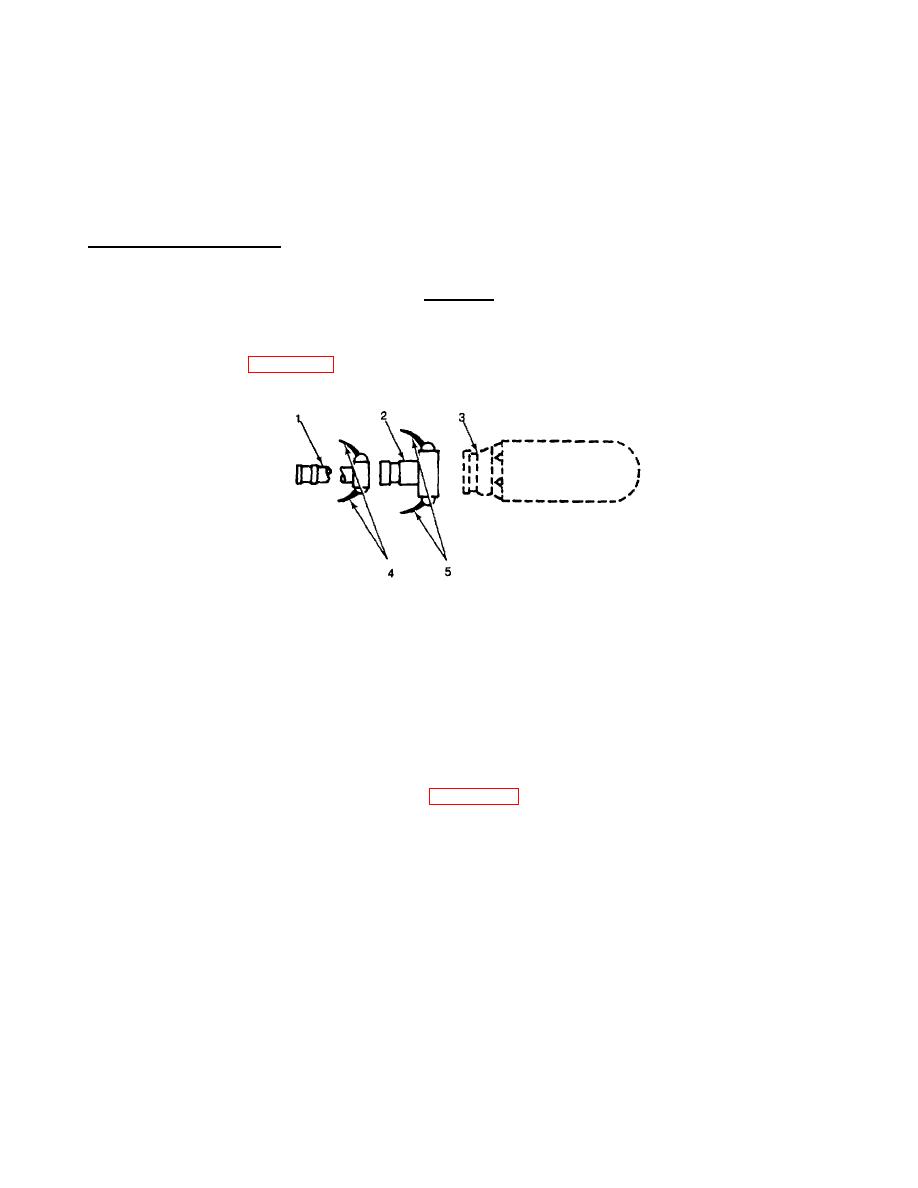
Push cam arms (4, Figure 2-22) on female end of reducer (2) forward to open position.
Figure 2-22. Tank, Reducer and Hose Assembly
CAUTION
To prevent leakage, dose both cam arms at the same time.
Do not strike cam arms too close. Damage to couplings could result.
(3)
Connect female end of reducer (2) to male fitting on storage tank fitting (3). Close cam arms (4).
(4)
Push cam arms (5) on 2 in. X 20 ft rigid-walled suction hose (1) forward to open position.
(5)
Connect hose (1) to reducer (2) attached to storage tank fitting (3). Close cam arms (5).
(6)
Locate suction and discharge ports (1 and 2, Figure 2-23) on 125 GPM pump.
2-43


