TM 10-4320-317-13
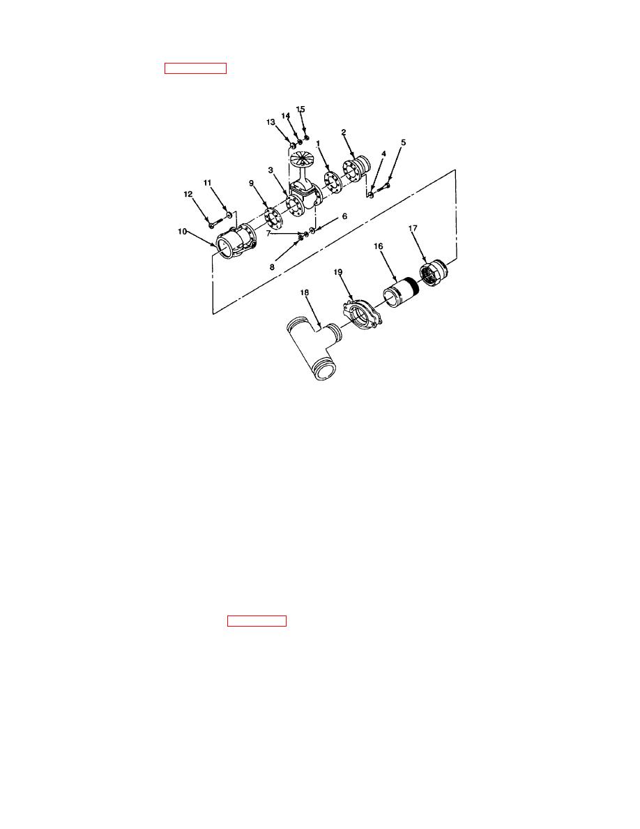
(11) Place gasket (1, Figure 2-20) on 4-inch flange adapter (2). Place 4-inch gate valve (3) on flange adapter (2).
Align holes in each part of assembly.
Figure 2-20. Discharge/Filler Hose Assembly
(12) Place flat washers (4) on eight bolts (5). Insert bolts (5) through openings in adapter (2), gasket (1), and gate
valve (3).
(13) Place flat washer (6), lockwasher (7), and hex nut (8) on each end of eight bolts (5).
(14) Tighten hex nuts (8) until lockwashers (7) engage and parts are firmly together.
(15) Place gasket (9) between 4-inch female coupling half (10) and Cinch gate valve (3).
(16) Align holes in each part of assembly, and place flat washers (11) on eight bolts (12). Insert bolts (12) through
openings in coupling half (10), gasket (9), and gate valve (3).
(17) Place flat washer (13), lockwasher (14), and hex nut (15) on each end of eight bolts (12).
(18) Tighten hex nuts (15) until lockwashers (14) engage and parts are firmly together.
NOTE
The anti-seizing tape is to be wrapped in the same direction as the pipe threads.
(19) Wrap anti-seize tape (Item 10, Appendix E) around threads of Cinch coupling pipe fitting (16). Screw coupling
pipe fitting (16) into male coupling half (17).
2-41


