
TM 10-4320-317-13
(3)
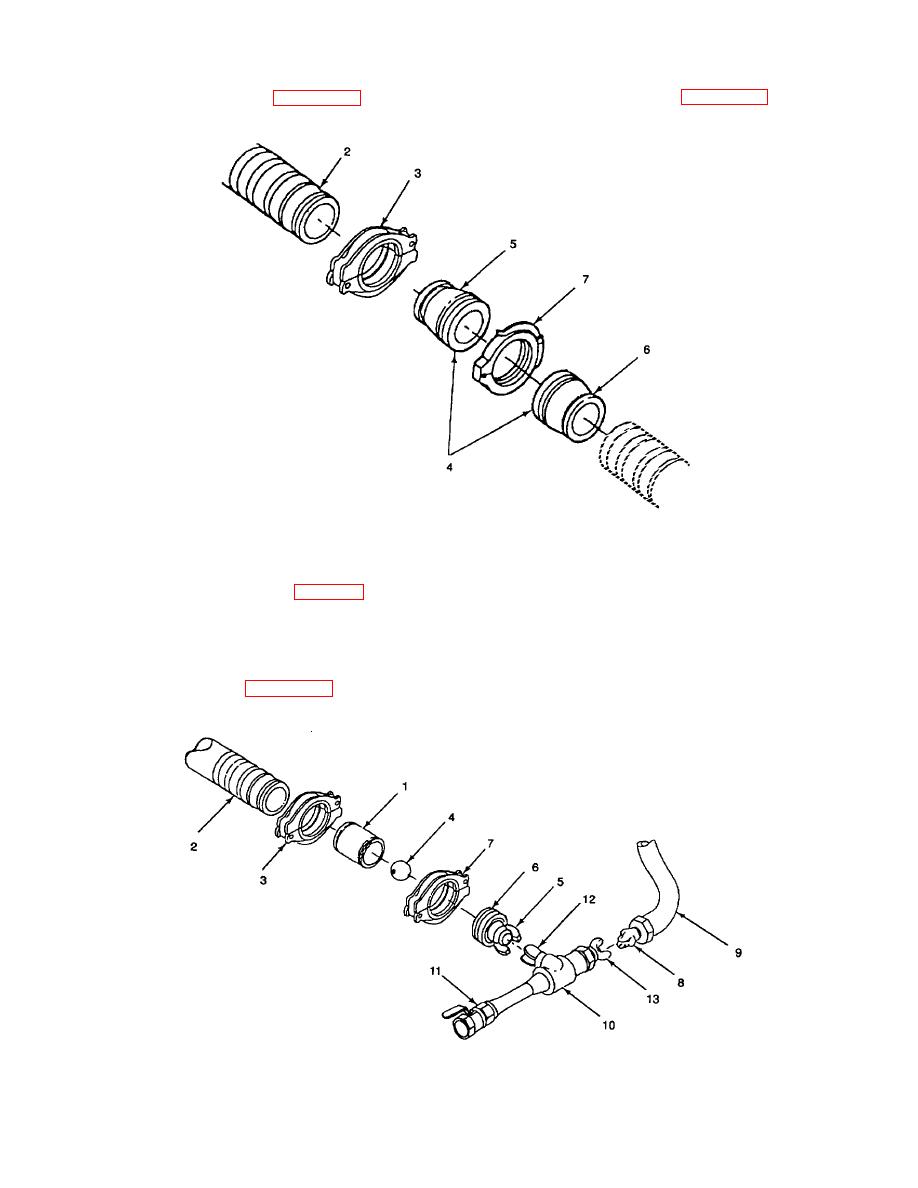
Locate ball receiver (4, Figure 2-33), consisting of two 8 X 6 inch reducers (5 and 6, Figure 2-33). One reducer
has been modified to prevent displacement ball from being ejected from ball receiver.
Figure 2-33. Ball Receiver
(4)
Connect 6-inch end of unmodified reducer (5) to downline end of first hoseline segment (2) using grooved-end
pipe boltless coupling (3) (para. 2-8.b.).
(5)
Locate 8-inch snaplock coupling (7). Open coupling.
(6)
Fit halves of snaplock coupling (7) over joined ends of reducers (5 and 6). Close coupling (7) over reducer (5
and 6) ends. Lock snaplock coupling (7).
(7)
Connect nipple (1, Figure 2-34) to upline end of first hoseline segment (2) using boltless coupling (3) (para. 2-
8.b.).
Figure 2-34. Displacement Ball
2-56
