
TM 10-4320-317-13
(8)
Place wet displacement ball (4) inside nipple (1).
(9)
Locate pneumatic coupler (5) and modified end cap (6) (with tapped hole). Attach pneumatic coupler (5) to
modified end cap (6).
(10) Connect modified end cap (6) with pneumatic coupler (5) to end of nipple (1). Use boltless coupling (7) (para. 2-
8.b.) from displacement and evacuation kit.
(11) Locate pneumatic coupler (8). Screw pneumatic coupler (8) into air compressor line (9).
(12) Locate ejector assembly (10), ball valve (11), and two pneumatic couplers (12 and 13). Install pneumatic couplers
(12 and 13) on threaded fittings on ejector assembly (10).
(13) Install ball valve (11) on end of ejector assembly (10). Close ball valve (11).
(14) Connect ejector assembly (10) to end cap (6) by connecting pneumatic couplers (5 and 12).
WARNING
Stand clear of receiver during displacement process. Hoseline may jump when displacement ball
arrives at receiver.
(15) Pressurize hoseline to 80 to 90 psi (551 to 620 kPa). Displacement ball (4) will be forced through hose, displacing
any residual water. A sound will be heard when the ball reaches receiver.
NOTE
If ball gets stuck, straighten kinks in hoseline. It may be necessary to increase air pressure. Do
not exceed 150 psi (1034 kPa).
(16) Shut off compressor when displacement ball (4) reaches receiver (6, Figure 2-33).
(17) Open snaplock coupling (7) connecting two reducers (5 and 6). Pull snaplock coupling (7) back and separate two
hinged coupling halves of snaplock coupling (7). Set snaplock coupling (7), displacement ball (4, Figure 2-33), and
modified reducer (6, Figure 2-34) aside.
(18) Remove boltless coupling (3) (para. 2-8.c.) connecting unmodified reducer (5) to hoseline segment (2).
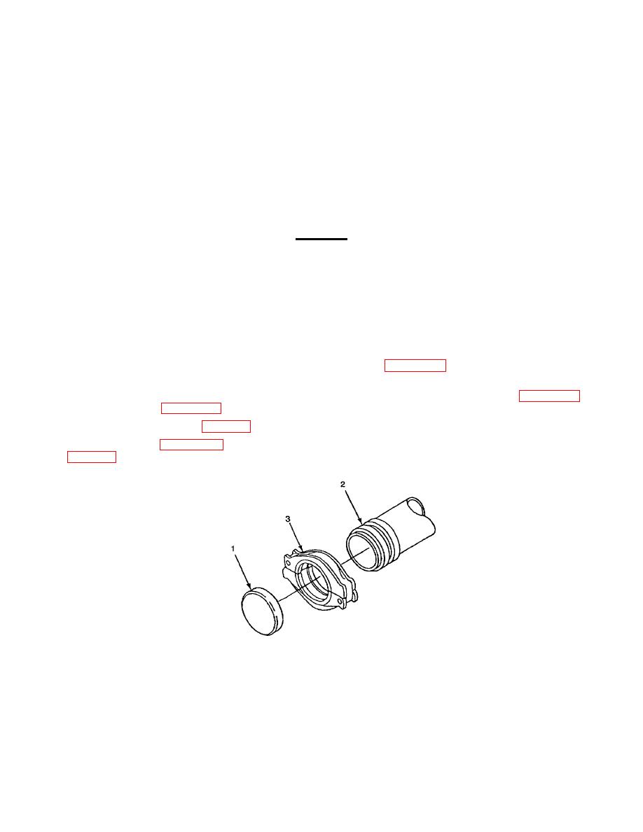
(19) Locate end cap (1, Figure 2-35). Connect end cap (1) to end of hoseline segment (2) with boltless coupling (3)
Figure 2-35. End Cap
2-57
