ARMY TM 10-4610-309-14
MARINE CORPS TM 10802A-14/1
0062 00
TACTICAL WATER PURIFICATION SYSTEM (TWPS)
UNIT MAINTENANCE PROCEDURES
CONTROL INSTRUMENTS
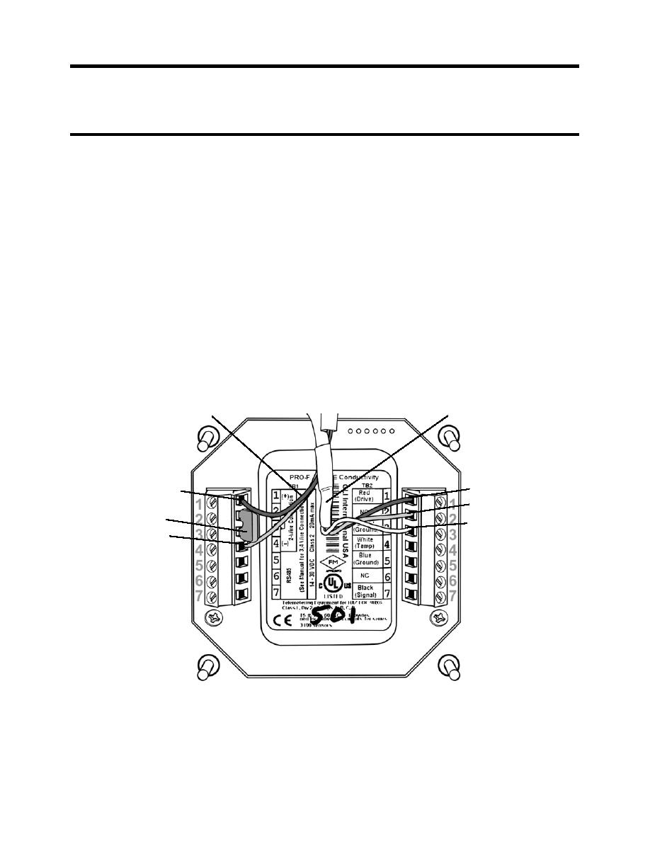
2. Install the new flow transmitter to the instrument/solenoid panel as follows (see Figure 2):
a. Put the DC input supply cable and sensor cable through the back of the retainer plate,
transmitter panel, and the transmitter panel mount gasket.
NOTE
The terminal color code label on the back of the flow transmitter may not match the
colors of the wires that are to be connected to the terminals. Follow the
instructions below when connecting wiring to the flow transmitter terminals.
b. Connect the sensor cable wiring to the new transmitter as follows:
1. Black wire to terminal 1 of TB2.
2. Red wire to terminal 2 of TB2.
3. Shielded ground wire to terminal 3 of TB2.
c. Connect the two wire DC input supply cable as follows:
1. DC+ Positive to terminal 1 of TB1 (black wire)
2. DC- Negative to terminal 4 of TB1 (red wire)
3. Jumper across terminals 2 and 3 of TB1.
d. Mount the transmitter to the transmitter panel using the four screws supplied with the
transmitter.
DC INPUT SUPPLY WIRES
SENSOR WIRES
BLACK WIRE
BLACK WIRE
RED WIRE
JUMPER
SHIELDED
GROUND
RED WIRE
WIRE
Figure 2. Flow Transmitter Wiring Terminal Designations.
3. Configure the flow transmitter with its associated sensor. Refer to Flow Transmitter
Configuration.
4. Run the TWPS unit and check the transmitter for proper operation.
0062 00-4


