ARMY TM 10-4610-309-14
MARINE CORPS TM 10802A-14/1
0062 00
TACTICAL WATER PURIFICATION SYSTEM (TWPS)
UNIT MAINTENANCE PROCEDURES
CONTROL INSTRUMENTS
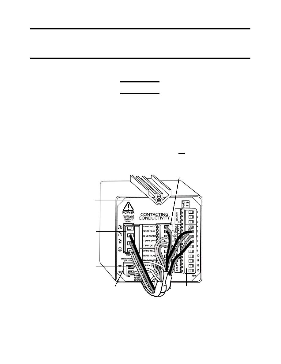
5. Connect the sensor wiring to the back of the transmitter as follows (see Figure 10):
CAUTION
Both conductivity sensors have two shield wires. One of the two shield wires has
shrink tube near the end of the wire. This shield wire is the outer sensor shield
wire and must be connected to the terminal at the TB2 module. If the two shield
wires are not connected to their proper terminals, the conductivity sensor and
transmitter may not function properly.
a. Outer shield wire (stranded wire with clear sheathing and a shrink tube near the end of
the wire) to the open terminal on module TB2.
b. Red sensor wire to the TB3 module terminal labeled DRIVE (RED).
c. Black sensor wire to TB3 module terminal labeled SENSE (BLK).
d. Inner shield wire (stranded wire with clear sheating without a shrink tube) to the TB3
module terminal labeled SHLD (INNER).
e. White wire to the TB3 module terminal labeled TEMP+(WHT).
f. Blue wire to the TB3 module terminal labeled TEMP-(BLU).
TB3 MODULE
BACK OF THE
CONDUCTIVITY
TRANSMITTER
TB1 MODULE
SHRINK TUBE ON THE
END OF AN OUTER
SHIELD WIRE
TB2 MODULE
TB4 MODULE
Figure 10. Conductivity Sensor Wiring Connections to the Conductivity Transmitter.
6. Configure the conductivity transmitter with the new conductivity sensor as described in
Conductivity Transmitter Configuration.
7. Run the TWPS and check for leaks and proper operation.
0062 00-20


