TM 10-4610-310-14
0112 00
PANEL RECEPTACLE (J1, J2, J3, J4, J5) - continued
3. Connect three wires (green, black, white) to rear of receptacle as previously noted. See Figure 3.
4. Install four screws (16), flat washers (15), and nuts (14) into panel receptacle (17). See Figure 2.
CIRCUIT BREAKER BLOCK (CR1 THROUGH CR5)
Removal
1. Remove two black electrical wires from terminal on circuit breaker block (25). See Figure 3.
2. Use a flat tip screwdriver and insert into slot at bottom of circuit breaker.
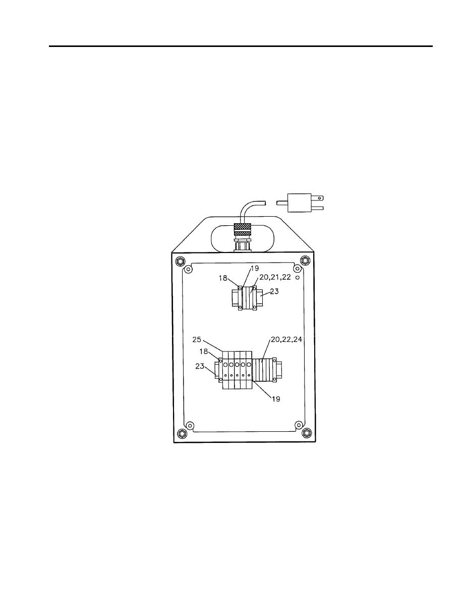
3. Pry the appropriate circuit breaker (25) from mounting channel (23). See Figure 4.
Figure 4. Internal Components.
4. Discard circuit breaker.
Installation
1. Position circuit breaker (25) into appropriate slot on mounting channel (23). See Figure 4.
2. Snap circuit breaker (25) into position.
3. Connect two black wires to terminals on circuit breaker (25). See Figure 3.


