TM 10-4610-310-14
0121 00
3. Reinstall the upper (3) and lower (5) journal bearings if removed. See Figure 1.
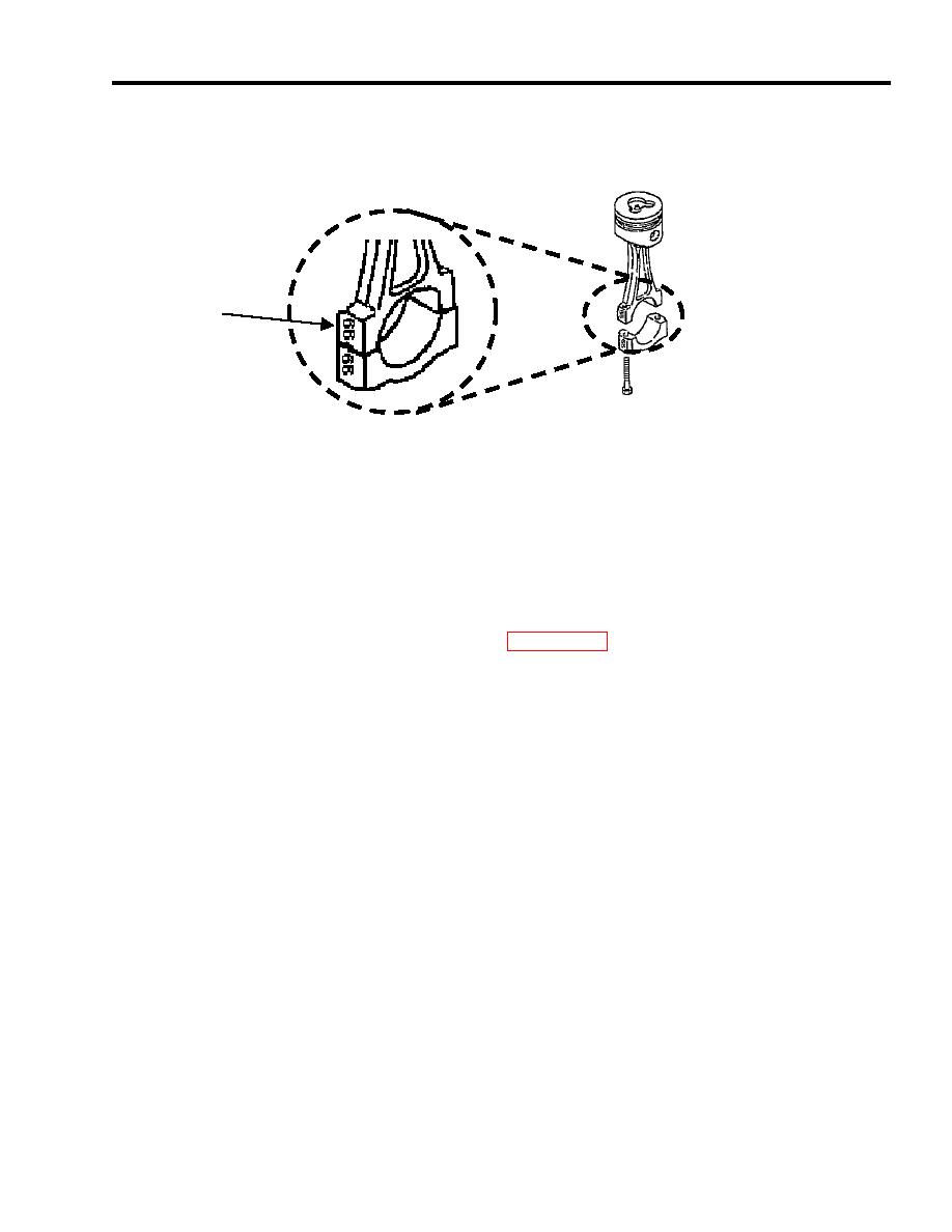
4. Mate the connecting rod cap (6) to the connecting rod. Ensure to match up the markings. See Figure 9.
CONNECTING ROD
MARKING
Figure 9. Connecting Rod Orientation.
5. Torque the connecting rod bolts between 16.65 20.27 ft-lb (2256 2746 N-cm).
6. After inserting the piston into the cylinder sleeve, measure the clearance. See WP0130 00.
7. The clearance between the piston and sleeve should be 0.04 to 0.06 mm (0.0015 to 0.0023 inch).
8. Reassemble the camshaft and the balancer shaft. See WP 0120 00.
END OF WORK PACKAGE


