TM 10-4610-310-14
0123 00
INSPECTION
1. Inspect the outer and inner rotor for signs of excessive or uneven wear. Fit inner rotor into outer rotor and
measure gap at various points.
2. Measure the clearances according to Table 1. Replace the oil pump if the clearances do not meet the service
limit minimum and maximum.
Table 1. Lubricating Oil Pump Clearances.
ITEM
STANDARD
SERVICE LIMITS
Outer Rotor Outside Diameter
29, -0.02, -0.04 mm
28.90 mm
(1.14, 0.0008, 0.002
(1.1378 inches)
inches)
(Minimum limit)
Internal diameter of the crankcase 29, +0.121, +0.100 mm
29.18 mm
port
(1.14, +0.005, 0.004
(1.1488 inches)
inches)
(Maximum limit)
Outer and Inner Rotor Width
8, 0, -0.03 mm
7.90 mm (0.31 inch)
(0.31, 0, -0.001 inch)
(Minimum limit)
Crankcase port depth
8, +0.05, +0.02 mm
8.10 mm (0.32 inch)
(0.31, +0.002, 0.0008
(Minimum limit)
inch)
Clearance Between the Inner and <0.14 mm (<0.006 inch)
0.25 mm (0.010 inch)
Outer Rotors
(Maximum limit)
Installation
Install the lubricating oil pump as follows:
1. Coat the inner and outer rotors with fresh lubricating oil.
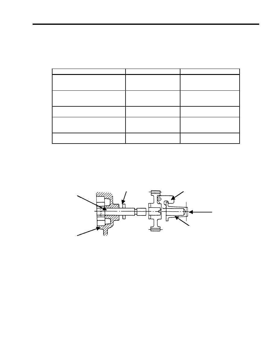
2. Install the inner rotor with pump shaft from outside of the crankcase cover. See Figure 2.
PARALLEL PIN
WEIGHT
PUMP SHAFT
PUSH IN
PIN
CRANKCASE
COVER
Figure 2. Lubricating Oil Pump Installation.
3. Insert the parallel pin into the pump shaft.
4. Install outer rotor.
5. Coat new O-ring with fresh lubrication oil and install into crankcase cover.
6. Install oil pump cover and three screws.
7. Install governor assembly pin. Ensure it is snapped into place.
8. Ensure the pin is snapped on to the weights on the governor assembly.
END OF WORK PACKAGE


