
TM 5-3800-205-23-3
BLACKOUT LIGHT MAINTENANCE - CONTINUED
0005 00
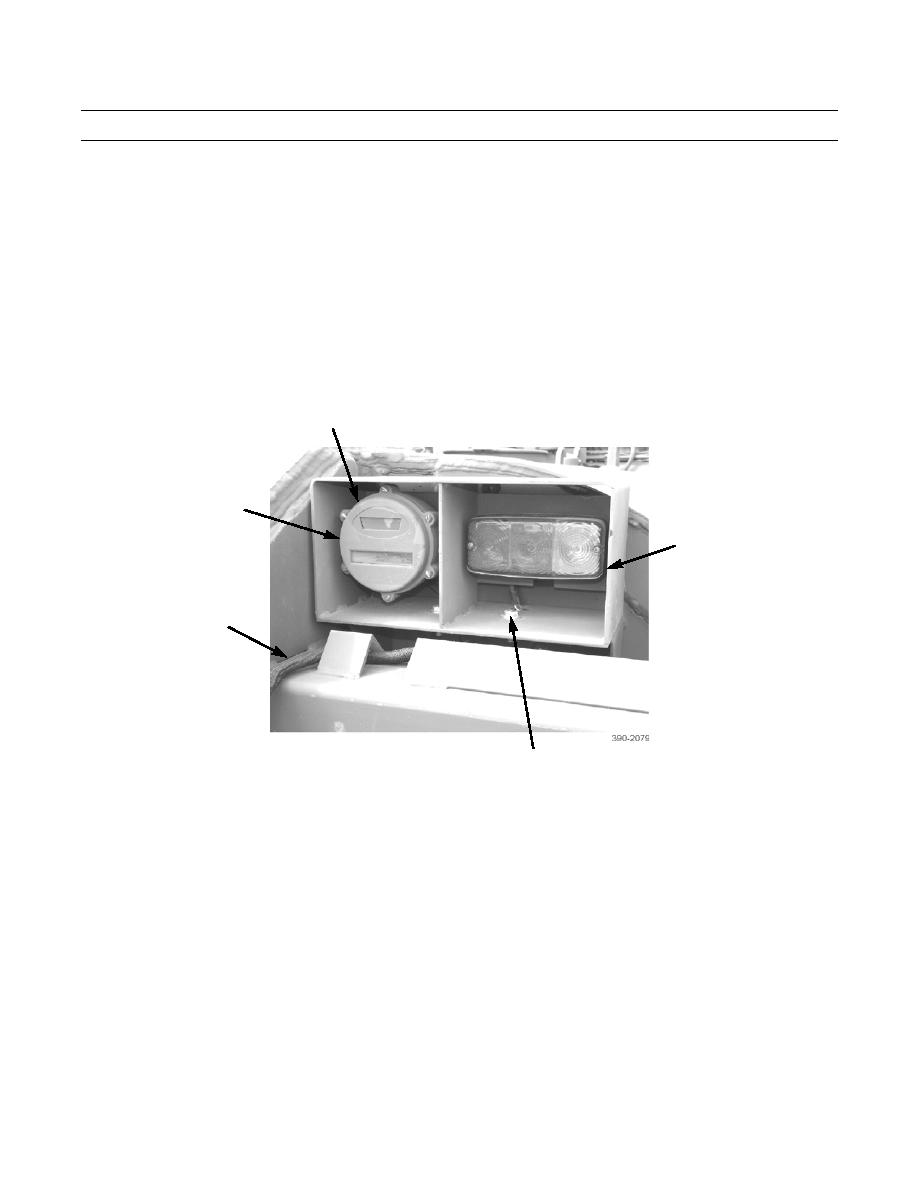
LIGHT ASSEMBLY REMOVAL
1.
Remove two nuts (12), lockwashers (13), washers (14), bolts (15), washers (16) and enclosure (11). Discard lockwash-
ers.
2.
Remove two screws (9) and washers (10) from back of light assembly (18).
3.
Disconnect two light assembly connectors from wiring harness connectors (17).
4.
Remove light assembly (18) from enclosure (11).
5.
Remove LEDs (Refer to LED Removal).
9,10 (HIDDEN)
18
11
17
12,13,14,
15,16
LIGHT ASSEMBLY INSTALLATION
1.
Install LEDs (Refer to LED Removal).
2.
Install light assembly (18), two washers (10) and screws (9) on enclosure (11).
3.
Connect two light assembly connectors to wiring harness connectors (17).
4.
Install enclosure (11), two washers (16), bolts (15), washers (14), new lockwashers (13) and nuts (12).
5.
Place battery disconnect switch in ON position (TM 5-3800-205-10-2).
6.
Check operation of blackout light (TM 5-3800-205-10-2).
END OF WORK PACKAGE
0005 00-4
