TM 5-4610-223-12
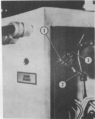
1. Terminal screws (2 reqd)
2. Toggle switch
3. Wires
Figure 4-43. Warning Light and Buzzer Toggle Switch Removal and Installation.
d.
Installation.
(1)
Attach wires (3, fig. 4-43) to terminal screws (1), then position switch (2) in mounting hole in control
cabinet.
(2)
Position plate (4, fig. 4-42) on switch (3) and secure switch and plate to control cabinet with nut (2).
4-55. START AND STOP CONTROL SWITCHES.
a.
General. The 13 START and STOP control switches are pushbutton operated. They are located on the inside
surface of the electrical control cabinet. They are used for starting and stopping the electric motors on the equipment.
The switches are all removed and installed in the same manner.
4-96