TM 5-4310-223-12
1.
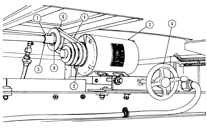
Drivebelt
5. Setscrew
2.
Motor drive pulley,
6. Agitator drive shaft
4 groove
pulley
3.
Agitator drive motor
7. Collar (2 reqd)
4.
Motor adjustment wheel
8. Setscrew
crank
Figure 2-21. Agitator Drivebelt Adjusting Points.
(h)
Open gate control valve CV-14 (1, fig. 2-16) in line from slurry weir box to sludge concentrator tank.
(i)
Open push-pull plug control valve CV-16 (1, fig. 2-22) on false bottom of sludge concentrator tank (6).
(j)
When clear water in upper portion of sludge concentrator tank has been established, open draw off orifice plug
control valve CV-17 (2). This will allow clear water to flow through draw off piping (5) to wet well tank (4).
(k)
Adjust chemical feed dosages as necessary to obtain satisfactory clarity characteristics of water in top of erdlator
tank.
(l)
Adjust speed of agitator if necessary to keep slurry blanket in rotation in accordance with paragraph (10), (a)
above.
Change 1 2-39

