VARIABLE SPEED CONTROL
The pilot wheel (A) -Fig. 5, for Variable Speed Drive
should not be turned except when the motor is running,
to avoid putting unnecessary strain on the variable
speed drive belt and variable speed drive pulley
assembly. The pilot wheel is turned clockwise to make
the drill press run faster, and counterclockwise to slow it
down.
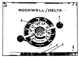
While changing speeds the pointer (B) Fig. 5, on the
speed dial will indicate the speed of the drill press.
A drag plug or "dampener" is provided to restrict the free
rotation of the pilot wheel. The drag plug is properly
adjusted at the factory so that the drill press will hold a
constant speed and will not change speeds even on long
production runs, but still the pilot wheel can be turned
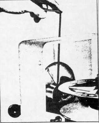
manually to change speeds as desired. If it ever
becomes necessary to change the adjustment, use a
long allen wrench and insert it down through the hole
located in the top of the guard, as shown in Fig. 6. Turn
the set screw (A) Fig. 6, clockwise to increase or
counter-clockwise to decrease the "dampener" pressure
on the pilot wheel.
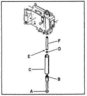
CHANGING LOWER SPINDLE ASSEMBLY
To replace the lower spindle assembly or to change drill
presses fitted with #2 Morse Taper Spindle to 1/2"
capacity key chuck spindle assembly, proceed as
follows:
1.
Lower the table to allow sufficient space between
the table and head to remove the spindle.
Fig. 7
Fig. 5
Fig. 6
2.
Lower quill approximately 2" to 4" and lock quill
locking nut
3.
Using a spanner wrench remove bearing closure nut
(A), and pull lower spindle (B) out of quill (C) Fig. 7.
4.
Remove garter spring (D), and key (E), Fig. 7.
Disengage sleeve (F) from spindle.
5.
Reassemble in reverse order.
5