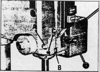
QUILL ADJUSTMENTS
The quill can be locked at any desired point in its travel
by tightening the quill locking nut (A) Fig. 8. This is an
especially desirable feature for set-up of tooling for
production type operations. After considerable use, Play
might develop between the quill and the head casting.
This play can be eliminated by loosening quill locking nut
(A) and lock nut (B) Fig. 8. The screw (C) can then be
turned clockwise which will draw the sprit halves of the
head casting together to compensate for wear. When
the final adjustment is accomplished tighten lock nut (B),
Fig. 8.
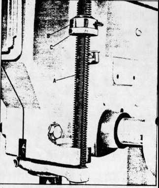
DRILLING HOLES TO DEPTH WITH HAND FEED
DRILL PRESS
When drilling one or two holes to a predetermined depth,
the graduations on the face of the depth stop rod (A)
Fig. 9, can be used.
When drilling a number of holes to a predetermined
depth, or if a more exact setting is required, proceed as
follows:
1.
Raise the locking sleeve (B) Fig. 9, and turn the
micro-nut (C) to the desired position on the stop rod (A).
2.
Lower the locking sleeve (B) so it will engage micro-
nut (C) Fig. 9. Lock sleeve (B) in place with thumb
screw if drill press head is mounted in other than vertical
position. When the drill press is mounted with the chuck
pointing "up", the locking sleeve (B) and micro-nut (C)
Fig. 9, should be reversed on the stop rod (A).
3.
When locking sleeve (B) is in place on the micro-nut
(C) Fig. 9, the micro-nut can not be turned. When a
change in depth is required, the locking sleeve (B) must
be raised, and while it is raised, turn the micro-nut (C)
the necessary graduation marks. Each mark represents
.002". Then lower the locking sleeve (B).
4.
The use of the micro-set stop nut will maintain the
same hole depth, no matter how many holes are to be
drilled. However, we recommend that the hole depth be
checked whenever a drill has to be sharpened or
changed.
Fig. 8
Fig. 9
6