TM 10-4610-310-14
0009 00
SETUP - continued
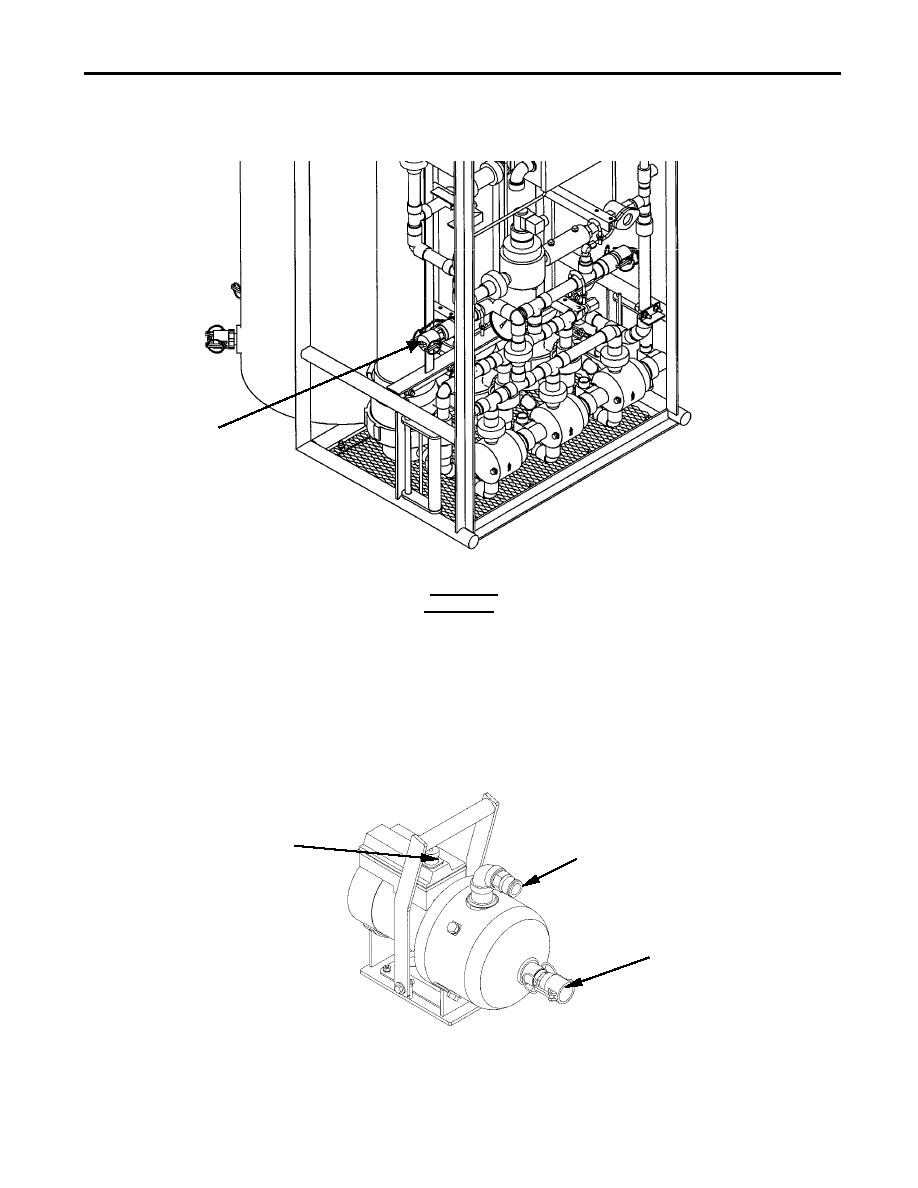
11. Connect one end of a reject hose (red) to the reject outlet on the UF assembly. See Figure 7.
UF REJECT (K)
Figure 7. Raw Water Reject Outlet Connection.
CAUTION
Do not place the UF reject fluid upstream of the raw water intake strainer. This may result damage to equipment
due to high turbidity intake.
12. Place the other end of the reject hose (red) in a suitable location downstream or down grade from the raw
water intake. A brine pit may be used.
13. Route the electrical cable P6 (gray) from the junction box on the UF module and connect it to the connection
(J6) on control module.
14. Position the backwash pump by the filtrate tank of the UF module. See Figure 1 and Figure 8.
PUMP
ELECTRICAL
DISCHARGE
RECEPTACLE
FITTING
SUCTION
FITTING
Figure 8. Backwash Service Pump.


