TM 10-4610-310-14
0046 00
MOTOR CONTROLLER
Inspection
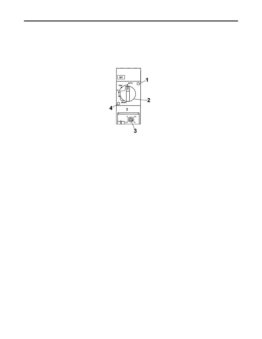
When the motor is running a flag can be seen through window (1). See Figure 4. In the event of a short circuit, a
flag can be visible through window (4) and the switch (2) will be rotated to TRIP location. The switch should
never be at OFF.
Figure 4. Motor Controller (raw water pump).
The motor Controller M1 is for raw water pump, M2 is for booster pump, M3 is for backwash pump, and M4 is
for distribution pump. The labels are affixed on the motor starter module.
1. Inspect the location of the switch (2) it should be set to AUTO. See Figure 4.
2. Reset the switch if it is pointing to TRIP.
a. Rotate the switch (2) counter-clockwise to RESET.
b. Rotate the switch (2) back to AUTO.
3. Ensure that the overload screw (3) is set to "4".
Resetting Circuit Breakers
The circuit breakers can be reset by switching them to off or reset and then back to on. See Figure 3
Closing
1. Ensure that all the Latches are placed out of the way.
2. Close the control panel. Ensure that the slot in the back of the switch is lined up with the shaft inside.
3. Hold the panel closed with one hand. Keep the hand on the panel.
4. Turn the safety tab (1) clockwise with the other hand. Do not let go of the safety tab (1).
5. Turn the switch (2) counter-clockwise. The safety tab (1) and the switch (2) should be squeezed
together.
6. Close the control panel and secure with latches.
END OF WORK PACKAGE


