TM 10-4610-310-14
0090 00
INSTALLATION
Before installation, wrap anti-seize tape on all the threads.
Flow Controller (5 GPM)
1. Refer to Figure 2 for this procedure section.
2. Install the flow controller (2) onto the solenoid valve (1) and adapter (3). Ensure that the arrow on the
flow control valve is pointing in the direction of the flow.
3. Install the tank inlet piping into the module. See WP 0085 00.
Flow Controller (8 GPM)
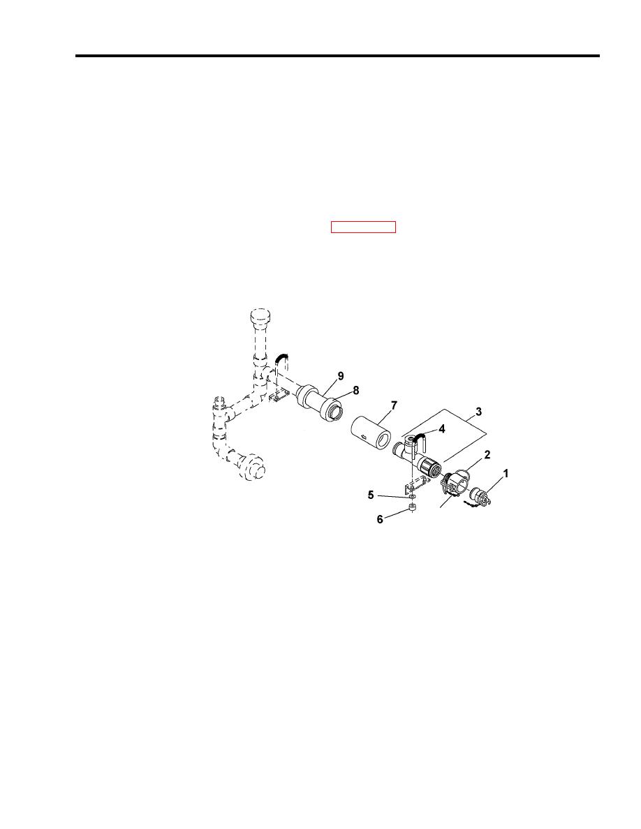
4. Install the flow controller (7) on to the check valve (9). Ensure that the arrow on the flow control valve is
pointing in the direction of the flow. See Figure 11.
Figure 11. Flow Controller (8 GPM).
1. Install the tee fitting (3) onto the flow controller (7).
2. Install the pressure gauge tubing onto the top branch of the tee fitting (3).
3. Install U-bolt (4) on the mount and secure with nuts (6) and washers (5).
4. Install female camlock (2) and dust plug (1) on the tee fitting (2).
Level Switch
1. Refer to Figure 7 for this procedure section.
2. Thread the level switch (2) into the holder (1).
3. Ensure the arrow (4) is facing up.
4. Feed the wires through the conduit and the junction box.
5. Ensure the wires are tagged and screw them onto the terminal block (TB1). See Figure 6.
6. Screw the conduit on both ends.


