TM 10-4610-310-14
0094 00
Vibration Mounts
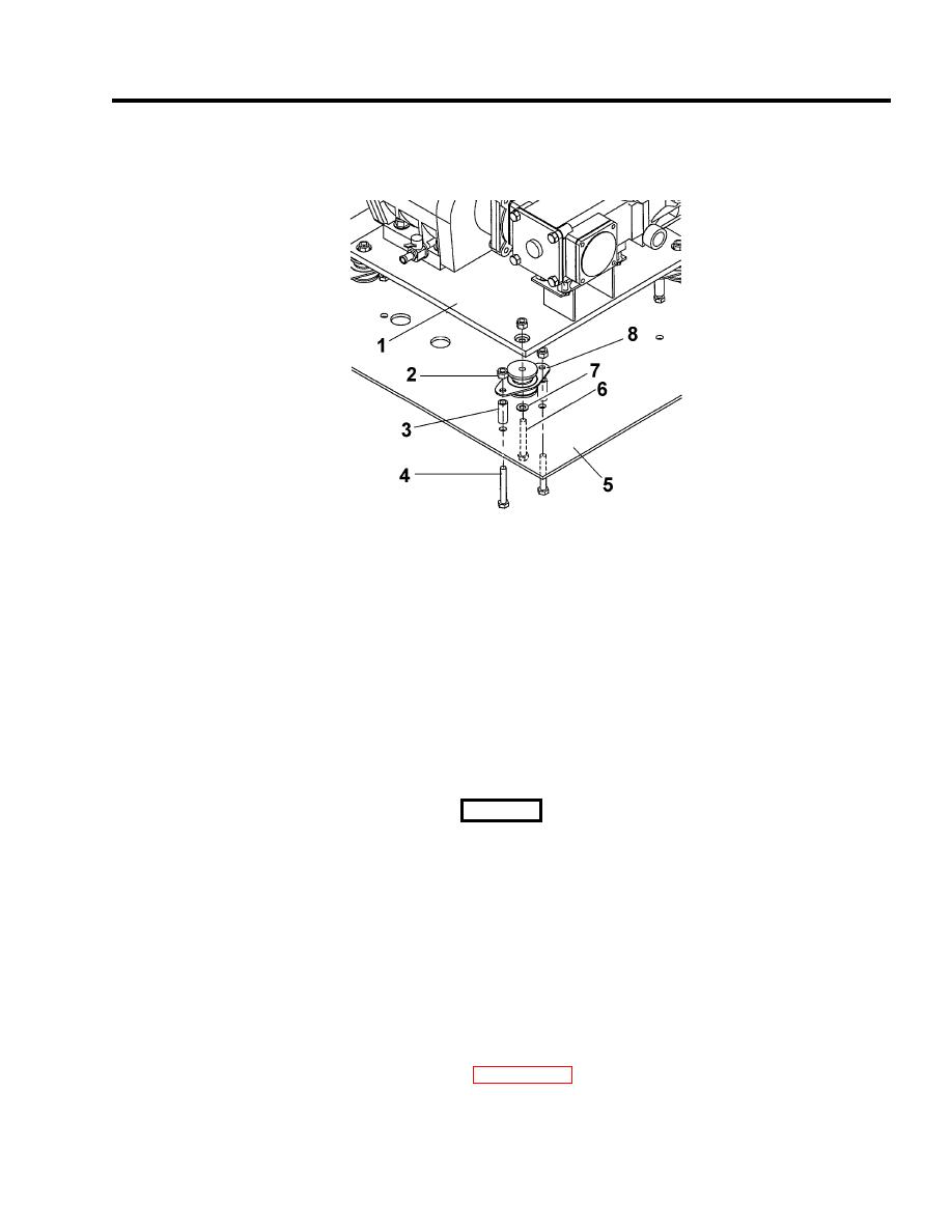
1. Remove two nuts (2), bolts (4), and center bolt (6). See Figure 6.
Figure 6. Vibration Mount Assembly.
2. Remove rebound washer (7), support tubes (3) and vibration isolator (8).
INSTALLATION
Vibration Mounts
1. Place vibration isolator (8) and support tubes (3) on the mounting plate (5).
2. Slide the bolts (4) through the mounting plate, support tubes (3) and vibration isolator (8). Secure with
nuts (2).
WARNING
Two personnel are required to install the diesel engine assembly on the module frame. Failure
to follow this warning may result in injury to personnel.
Diesel Engine Assembly
1. Place the diesel engine assembly (1) onto base plate (8). Secure engine to base plate with four nuts (2),
washers (3), and bolts (4). See Figure 5.
2. Install diesel engine assembly (1) and mounting plate (8) onto vibration isolators (9). See Figure 5
3. Secure the base plate (8) to the vibration isolators (9) with bolts (6), washers (7) and four nuts (5). See
Figure 5.
4. Install high-pressure pump and gearbox. See WP 0098 00.
END OF WORK PACKAGE


