TM 10-4610-310-14
0117 00
REMOVAL - continued
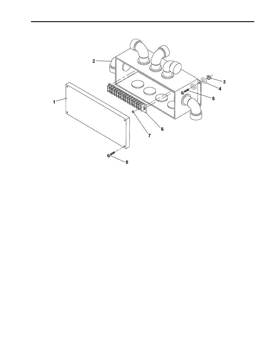
Figure 2. Junction Box Assembly.
3. Loosen four screws (8) and remove junction box cover (1). See Figure 2.
4. Remove all ground wires.
5. Remove all the wiring from the terminal block (6). Note the location of the wires and their numbers. See
Figure 3.
6. Remove all the conduits from the nine hubs (2). Note the locations of the hubs.
7. Remove the jumper strips between terminals 10 through 14. See Figure 3.
8. Remove four lock nuts (7) from the terminal block (8) and remove the terminal block (8).
9. Remove four screws (5), eight washers (4) and four lock nuts (3) and remove the junction box from the
module.
INSTALLATION
1. Mount the junction box on the module and secure with four screws (5), eight washers (4) and four lock
nuts (3). See Figure 2.
2. Mount the terminal block on the junction box and secure with four lock nuts (7).
3. Connect the jumper strip between terminal 10 and 11 and all the wiring on the terminal block (6). See
Figure 3.
4. Reconnect all the conduits from the nine hubs.
5. Ensure all the wires are in correct terminals and are labeled.
6. Connect all ground wires.
7. Replace the cover and fasten with four screws (8).


