
TM 5-3800-205-23-3
SUCTION INLET MANUAL VALVE AND VACUUM VALVE REPLACEMENT
THIS WORK PACKAGE COVERS
Suction Inlet Manual Valve: Removal, Installation
Vacuum Valve: Removal, Installation
INITIAL SETUP
Maintenance Level
Equipment Condition
Machine parked on hard, level surface (TM 5-3800-
Unit
205-10-2)
Tools and Special Tools
Tank lowered to ground (TM 5-3800-205-10-2)
Tool kit, general mechanic's (Item 33, WP 0045 00)
Parking brake engaged (TM 5-3800-205-10-2)
Wheels chocked (TM 5-3800-205-10-2)
Materials/Parts
Battery disconnect switch in OFF position (TM 5-
Rag, wiping (Item 31, WP 0044 00)
3800-205-10-2)
Sealing compound (Item 36, WP 0044 00)
Tank drained (TM 5-3800-205-10-2)
Foot valve assembly removed from stowage on suc-
Washer, lock (suction inlet manual valve replace-
tion inlet (TM 5-3800-205-10-2)
ment) (4)
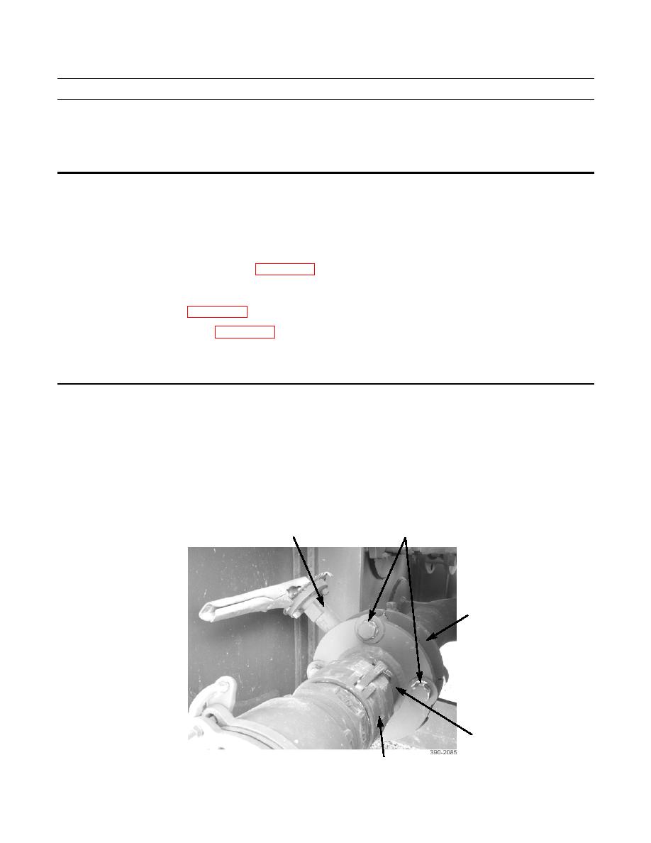
SUCTION INLET MANUAL VALVE REMOVAL
NOTE
Note position of suction inlet manual valve for installation.
1.
Remove four nuts (2), lockwashers (3), bolts (4), flange (6) with coupling (7), and suction inlet manual valve (1) from
suction pipe (5). Discard lockwashers.
2.
If necessary, remove coupling (7) from flange (6).
2,3,4
1
5
6
7
