
TM 5-3800-205-23-3
SUCTION HOSE FOOT VALVE ASSEMBLY REPAIR
THIS WORK PACKAGE COVERS
Disassembly, Assembly
INITIAL SETUP
Equipment Condition
Maintenance Level
Machine parked on hard, level surface (TM 5-3800-
Unit
205-10-2)
Tools and Special Tools
Tank lowered to ground (TM 5-3800-205-10-2)
Tool kit, general mechanic's (Item 33, WP 0045 00)
Parking brake engaged (TM 5-3800-205-10-2)
Shop equipment, common no. 1 (Item 24, WP 0045
Wheels chocked (TM 5-3800-205-10-2)
Battery disconnect switch in OFF position (TM 5-
Materials/Parts
3800-205-10-2)
Gasket
Foot valve assembly removed from suction inlet
(TM 5-3800-205-10-2)
Washer, lock (4)
DISASSEMBLY
1.
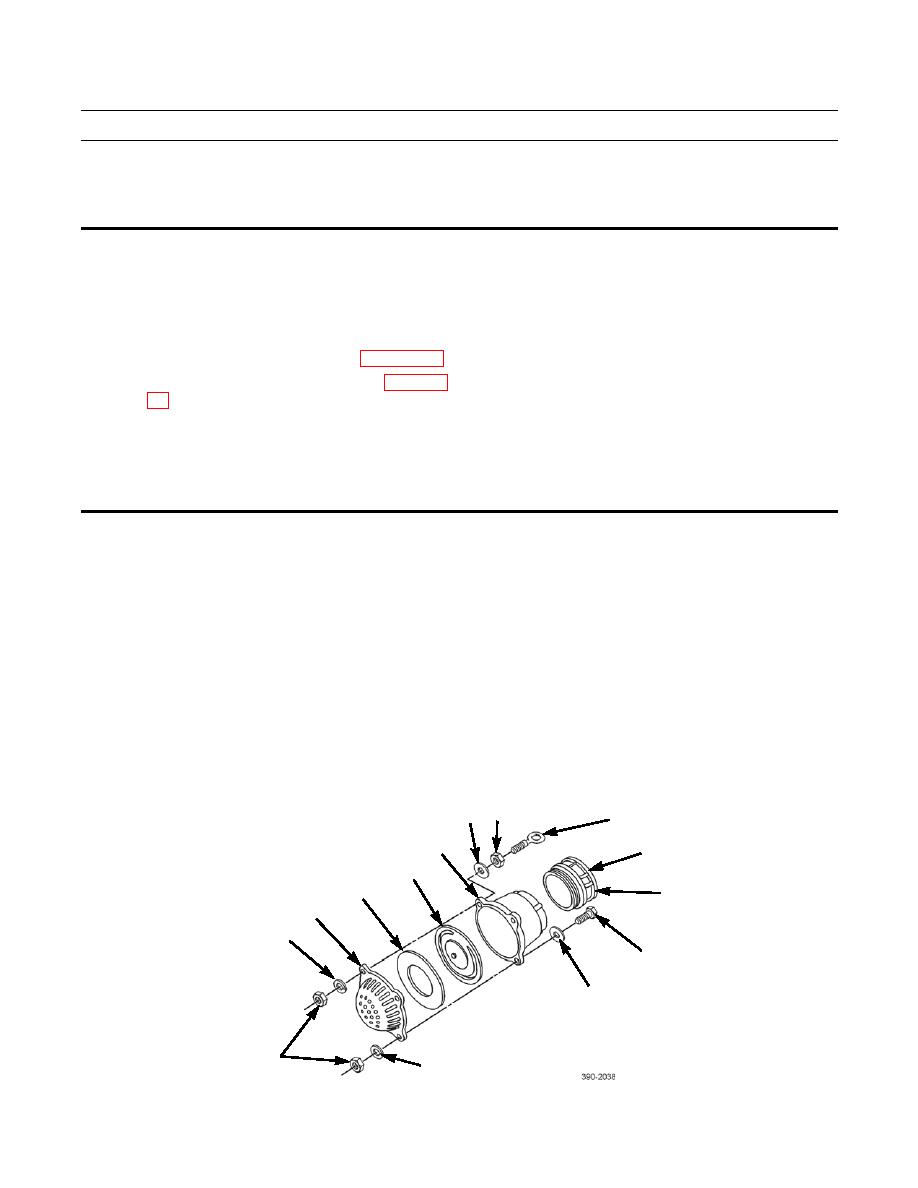
Remove gasket (10) from camlock fitting (9). Discard gasket.
2.
Place camlock fitting (9) in a vise. Use a strap wrench to remove foot valve body (5) from camlock fitting.
3.
Remove three nuts (12), lockwashers (1), bolts (11), and flatwashers (6) from head (2) and body (5). Discard lockwash-
ers.
4.
Remove remaining nut (12), lockwasher (1), and eyebolt (8). Discard lockwasher. As required, remove flatwasher (6)
and nut (7) from eyebolt.
NOTE
Note orientation of components as they are disassembled to ensure correct assembly.
5.
Separate head (2), plate (3), check (flapper) valve (4), and body (5).
7
6
8
5
9
4
3
10
(HIDDEN)
2
1
11
6
12
1
