TM 5-4610-223-12
(3)
Loosen screws (5, fig. 3-10) and slide slurry feeder drive motor (3) toward speed reducer drive pulley (1).
(4)
Remove drivebelt (2) from pulleys (1 and 4).
(5)
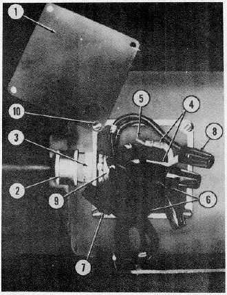
Remove four screws (10, fig. 4-37), and junction box cover (1).
1. Junction box cover
6. Motor electrical lead
2. Cable connector
wires, black
3. Connector nut
7. Tape
4. Electrical cable lead
8. Connector nuts (3 reqd)
wires
9. Ground lead wire
5. Screw, machine
10. Screw, junction box cover
1/4-20 x 1 in.
mounting (4 reqd)
Figure 4-37. Chemical Slurry Feeder Drive Motor, Electrical Junction Box.
(6)
Loosen screw (5) and disconnect ground lead (9).
(7)
Remove tape (7), and unscrew connector nuts (8) from leads (4 and 6).
4-83

