TM 5-4610-223-12
(4)
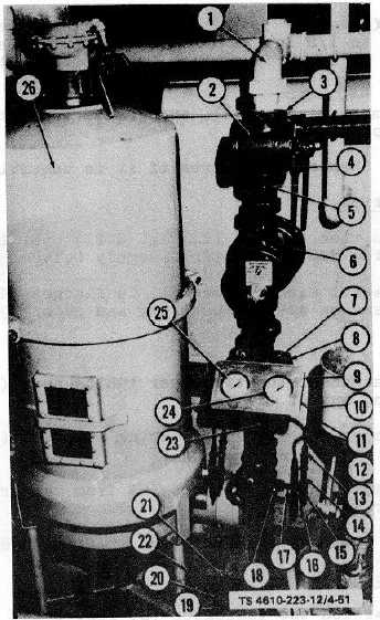
Install bushings (18), nipples (17), tees (15), and draincocks (16).
(5)
Install nipples (14), adapters (12), and draincocks (13) to tees (15).
(6)
Attach tubes (11) to elbows (10) and adapters (12) with J tube nuts (9).
4-69.
RAW WATER FLOW INDICATOR.
a.
Removal.
(1)
Remove nuts (3, fig. 3-21), washers (2) and screws (1) securing the flanges (4) to raw water flow indicator
assembly (5).
Figure 4-51. Flow Controller Valve and Fitter Gages.
4-111