TM 10-4610-310-14
0102 00
PLC OUTPUT CARDS 1 AND 2
Removal
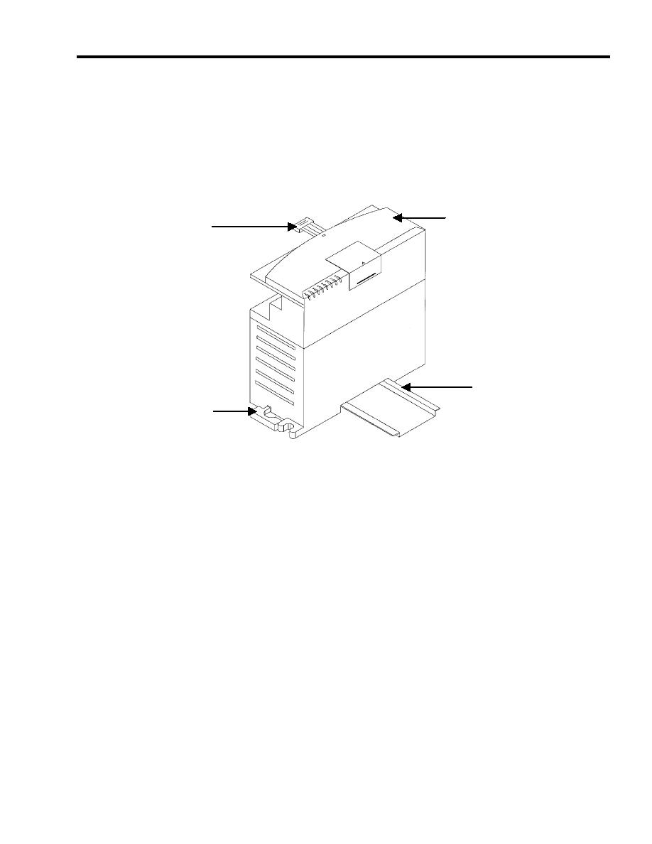
1. Open cover and make note of number and location of all wires. See Figure 6.
2. Remove all wires.
3. Unplug the ribbon connector from the adjacent module.
COVER
RIBBON
CONENCTOR
DIN RAIL
DIN RAIL
LATCH
Figure 6. PLC Output Card.
4. Pull out the DIN rail latch.
5. Tilt the output card towards the top and remove it from the DIN rail.
Installation
Push the DIN rail latch in.
Press the output card onto the DIN rail.
Connect all wires. Observe the tags and prior note for installtion.
MAGNETIC CONTACTOR (CR1)
Removal
1. Make note of number and location of all wires on heater control relay magnetic contactor. See Figure 4.
2. Remove wires from magnetic contactor.
3. Insert screwdriver into release clip. Push down to release.
4. Remove magnetic contactor from mounting socket.


