TM 10-4610-310-14
0104 00
INSTALLATION - continued
Sampling Hose
1. Refer to Figure 1 for this procedure section.
2. Install the sampling hose (3) on the piping (1) and tighten clamp (2).
Product Inlet Spool Piece
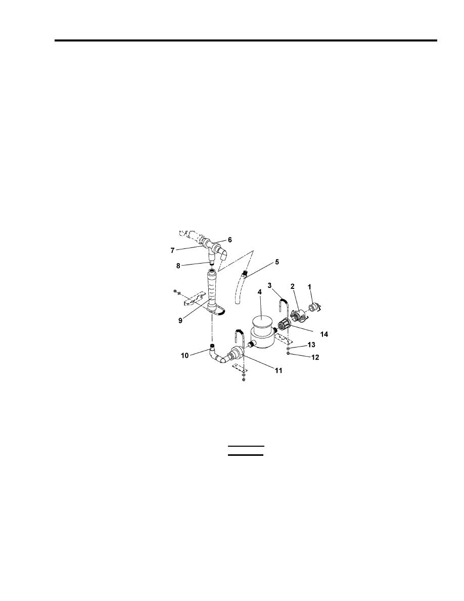
1. Assemble the spool piece into one unit if taken apart. See Figure 11.
a. Install 3-way ball valve (6), flow meter (9), totalizer (4), adapter (14).
2. Place the spool piece in the module.
3. Tighten union (7).
4. Install U-bolts (3), and secure with nuts (12) and washers (13).
5. Install female camlock (2) and dust plug (1) if removed.
Figure 11. Product Inlet Piping.
Product Outlet Spool Piece
1. Refer to Figure 3 for this procedure section.
CAUTION
Install the check valve in correct direction of the flow. Damage to equipment may result.
2. Install the check valve (4) on the 3-way valve (6). Tighten union (5). Ensure that the arrow on the check
valve body is in line with the flow.
3. Install tee fitting (8) on the piping.
4. Install chlorine tubing (7) on the tee fitting (8).
5. Install U-bolt (3) and secure with nuts (9) and washers (10).
6. Install male camlock (2) and dust cap (1) if removed.


